This thread has been locked.

If you have a related question, please click the "Ask a related question" button in the top right corner. The newly created question will be automatically linked to this question.

LM2907 frequency to voltage converter

Other Parts Discussed in Thread: LM2907-N

hi sir,

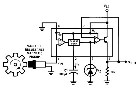
im using LM2907 to convert frequency to voltage..i use optical encoder(sensor) to transfer signal to the LM2907 circuit. I connect my sensor to three-phase induction motor to count rpm and send the frequency(SIGNAL) to my f/v circuit. the circuit I used is from Ti's literature number SNAA088 (AN-162 LM2907 TACHOMETER/SPEED SWITCH BUILDING BLOCK APPLICATION) [page 5]...but I cnt get the output coltage..I also upload my circuit in breadboard...the output signal from my sensor also I upload here...some of circuit I try also I upload here...so anybody can help me to solve my problem..tq so much...

Details of my circuit :-

at pin 2 = 0.01microF (ceramic 103)

at pin 3 = 100k and 1microF (ceramic105)

at pin 4 =100k and 10microF (+/-)

  • Hello Rathan,

    The 8-pin version has the input threshold set at ground. It is designed for magnetic sensors that would output a bipolar signal that would go plus and minus crossing through ground.

    Read the first paragraph of the "Applications Information" section very carefully...

    You must get within 50mV of ground to get through the hysteresis and thresholds. Your sensor output does not swing all the way to ground.

    Try AC coupling your signal through a 0.1uF series capacitor to remove the gound reference and swing ± around ground. Otherwise, you need to use the LM2907 and set the comparator threshold pin (11) to the midpoint of your sensor signal.

    Regards,

  • Tq sir for your kind reply..sir I wan to ask something..my sensor have (+/-) and signal .so I need connect my signal wire only to my circuit ? without ground ?

  • Hello Mathan,

    Connect the sensor as you have it now (GND to GND, + to supply), but place a 0.1uF in series (between) the sensor output "SIG" and the LM2907 pin 1.

    The capacitor blocks the DC component and passes the AC component. The voltage on the LM2907 pin 1 should now be between about +2.5 and -2.5V, meeting the requirement that the LM2907 input signal must pass through 0V.

    Also - make sure you are looking at the LM2907-N datasheet, which is the original National datasheet. It has much more information.

     http://www.ti.com/lit/gpn/lm2907-n

    Regards,