This thread has been locked.

If you have a related question, please click the "Ask a related question" button in the top right corner. The newly created question will be automatically linked to this question.

INA180: Setup advice.

Part Number: INA180
Other Parts Discussed in Thread: INA240, OPT3001

Hi All

I have not used a sensing amp before and would like to have some advice.

I am planning to use the INA180 for two applications.

  1. Monitoring solar strength from the 5V 240mA. I plan to keep an simulation load (20 ohms ) and use that the monitor the max current output.  Would that be the best approach?

  2. I would also like to test if solenoids are connected to my system, and therefore would like to add another INA180 to the output of my DC-DC step up. The Step up connect directly to a H-Bridge circuit, therefore monitoring the current going into the  H-Bridge will give me an indication if its be connected correctly.  Would this be the correct approach?

How would i calculate the sense resistor to use and how to determine the current consumption from the voltage output?

  • Dharmesh,

    1. A simulation load of 20 ohms will kind of work, but you must be careful to understand that as you change the voltage from 0V to 5V to create varied load currents, you will also be changing the common mode of the device.  This will affect the error performance of the part.  In terms of offset, it could likely be in your favor as with a common mode of 0V, the offset will be under 150uV guaranteed, but at larger values, it could be up to 500uV.

    Another thing to note is the swing to ground spec.  If you are trying to measure currents down near 0mA, there will be some point where the amplifier goes non-linear.  For the INA180, this is around 5mV.

    For shunt resistors,  A 1 ohm shunt resistor with 240mA through it creates 240mV of input voltage, and using the A1 version of the device, is x20, so that would produce 4.8V on the output of the shunt resistor.  So overall, that would be about the largest value I would expect, but lower values offer lower power consumption and smaller voltage drop.  If you have this device in a high side configuration, know that the bus rail at full 240mA is no longer 5V but 4.76V.  Current consumption through the shunt is just I=V/R.  For reference, the output of the current sense amp is Ishunt * Rshunt * Gain.  So, if you had a 20mOhm shunt, a gain of 200 (A4 device), and your current of 240mA, then you would get .24 * .020 * 200 = 0.96V on the output.  The output must be lower than the Vs supply of the device, and just a little lower than that to account for swing-to-supply-rail specs.

    The error as you get lower and lower in current will increase.  There is a sidebar widget in the product page that can help you see what the error curve for your application will look like.  I put in a few values and here are the results.

    To better understand implementations, the data sheet specs and all the sources of error in current sense amplifiers, there is a training video series we made that can help.

    2. Depending on how you implement the current sense amp in the circuit, there are things to consider.  The INA180 may not be the best choice for a solenoid application if it's not a low-side or high-side only implementation.  For that, I would strongly recommend you look at the INA240, which excels in PWM and in-line solenoid and motor control applications.  Also, we produce tech notes that are like very short, 2 page app notes that can help you understand implementations and get product recommendations.  There are 5 tech notes already on solenoid and motor control.  Please take a look and see if they match your desired implementation.

  • Hi Jason

    Thank You for your reply.

    I forgot to mentioned, the amps will be powered using 3.3V which is what the microcontroller will be using as well.

    If use a 0603 or 0805 1 ohm resistor would that be good enough?

    1. From what have I have understood, the solar panel always outputs 5V but with a variation in the current output. If the current load is much higher then what the solar panel can output, then voltage does drop. If this is the case, where the power output of the solar panel is dropping when a 20ohm was to be used, what would be the effect?

    Measuring current in the 0 mA range will be not be a requirement for the application. Anything less than 10mA, will be considered low and in my solar gauge(GUI) I can show it as low or almost no charge at all.

    According to the graph, errors will increase once consumption is about 50mA, at this stage the application will report the solar strength as low , so it’s not trivial to have accuracy like a amp meter or lab instrument etc.


    2. In regard to using the INA180 for a solenoid application, the intention is to have economical way to confirm that the solenoid is connected. The intention is not measure the current in a bi-directional way but to measure the current consumption on the output of the DC-DC step up. This way the current can be measured independently without worrying about the polarity of the solenoid. The solenoid are rated to 2.5A with 9V, and the DC-DC only powers the Solenoid circuit, therefore if the solenoids are connected then the output from the amp should reflect this.

    I am anticipating the simple INA180 will be adequate?
  • Hi Dharmesh,

    Jason is out of the office so I will jump in to provide you feedback.

    1. If you are using the solar panel as the common mode voltage of our device, that is fine. The INA180 common mode voltage is: –0.2 V to +26 V. As long as you stay within this range it should be fine. Do have in mind, changes in VCM will affect the accuracy of the device. Also, I wanted to mention that the INA180 operate from a single 2.7-V to 5.5-V power supply. In case you decide to power the device with the solar panel, the voltage can't go lower than 2.7-V. Seems like you are using the same 3.3-V rail as the micro controller, so that's great.

    2. The INA180 will suffice for the application you are describing. 

    3. About the value of the shunt resistor. The 1 ohm resistor will not work if you have the 240mA current and a Vs= 3.3V. As Jason mentioned,  a 1 ohm shunt resistor with 240mA through creates 240mV of input voltage, and using the A1 version of the device, is x20, so that  should produce 4.8V on the output of the shunt resistor.  In your application, the output of the device will saturate at 3.3V due to your supply voltage. 

    Please refer to our video section 4: How to chose and appropriate shunt resistor. This video will help you calculate the value needed for your application.

  • Dear Mayrim

    I will have a look at the video in regards to the shunt resistor calculation.

    Another issue that has crossed my mind was that i do not need to monitor continuously and therefore aim to save power as my applications are battery powered.

    If i was to place either a cheap LDO or load switch to output 3.3V to the VCC pin of INA180, then switch off the device but still have current flowing via the shunt resistor what effect would that have and would the device still be consuming some power?

    The issue arises on the DC-DC-Step up application for the solenoid, as when the Step-up is off there is still VIN which is at VOUT, i am presuming there will be some current draw still. Would this be correct?

    Where as when it comes to the solar application, this is not an issue as i am measuring as simulation and the load is connected via a load switch.
  • Just preforming some calculation and after watching the video.


    1. In regards to calculating Rsh max, would I be correct in saying that Vout is the output going to my ADC, which should not be above 3.3V?


    As my DC-DC step will output 9V 1A, but I have kept ILoad max to 1.5A for my calculation so I have some flexibility. 

    Presuming Vout is 3.3V and not 9V, 

    My shunt calculator will be 0.11R for my DC_DC application, which is outputting 9V 1.5A 

    And for solar application 

    My shunt calculator will be 0.66R for my DC_DC application, which is outputting 5V 0.240mA.  

    Does this seem correct 

  • Dharmesh,

    regarding 1 - yes, you should size you shunt appropriately so that the maximum current * rshunt * gain < adc max input voltage.

    Also remember to account for a little headroom - if you power the INA180 with 3.3 and expect 3.3V output, it won't reach 3.3 because of the amplifier headroom needed.  See this article for more on that.  However, if you only need to measure 1A and scale for 1.5A, then you're probably just fine.

    for your other application, I'm assuming you meant 5V 0.240A and not 5V 0.240mA.  With a 660mΩ shunt and a gain = 20, then that would produce 3.168V at 240mA, which is reasonable.

  • Hi Jason

    Thank you for your reply. Yes you are correct it is 240mA.

    I will be placing a sample order forthe INA180 and testing them out on a test PCB.

    The aim of measuring the current on the 5V 240mA application is also determine the LUX of the light, i am not sure if this is possible to determine this from solar current output or is this a matter of building some correlation table ?

    For the application of 9V 1.5A, we need to  determine if external device is connected correctly, which i guess will be straightforward.

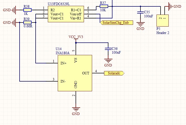
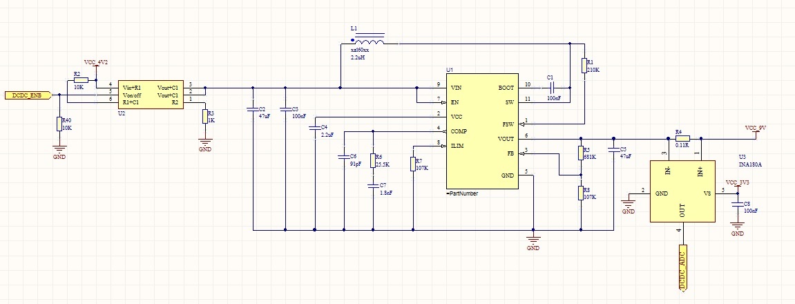
    I have attached my schematic diagram of the INA180, can you advice me if this circuit will be good enough or do i need to have additional filters?

    5V 240mA

    9V 1.5A


    The INA180 does not have a sleep mode enabled and when its not measuring any current i would like to conserve energy, would it be advice-able to power the device directly from GPIO pin of my micro-controller as there current requirement of the device is only 300uA? This way i can do away with any load switch?

    From the datasheet it mentions there are two pin configurations , how would i determine which configuration is being ordered as i could not find information the part number indication? 

    Thank You

  • The schematic looks ok to me, and the only thing I usually recommend is adding a spot for a low-pass pi filter to the front end.  You can always not populate the cap and install 0 ohm resistors if you don't need it, but it's great to have if you do, and it's good for debug as well.

    It looks something like this:

    Next, about pin configurations, they are labeled A and B - see below:

    You can tell them apart in the ordering table at the end of the data sheet because it says INA180A1 or INA180B1 and so on.  The package markings are on the ordering table as well, so you can see which one you have if all you have is the physical part in your hand.

    You can power the device from a GPIO switch, but make sure to have a bypass cap on it for the power supply still.

    Another thing to think about is that you are driving an ADC, which means you're going to be pulling some current from the INA180 output drive circuitry, which is pretty weak.  Adding an RC filter to the output, and possibly even a buffer IC, is something to consider.  There is a parameter called "closed loop output impedance" which you can use to determine if a filter will be stable.  See this article and this app note for more. 

    One final note - there is a lux light sensor that TI makes (OPT3001) and it measures darkness up to bright sunlight with good IR rejection and has an i2c interface.  Not sure if that helps, but I thought I would throw it out there.