Hi,
I need to build up a circuit to detect nsec width pulses. Naturally I found this thread:
http://e2e.ti.com/support/amplifiers/high_speed_amplifiers/f/10/t/167314.aspx?pi196062=1
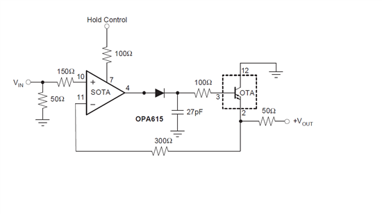
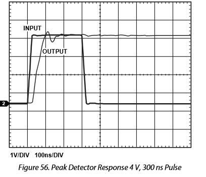
I built a circuit with reference to Fig. 48 of the OPA615 datasheet: http://www.ti.com/lit/ds/sbos299e/sbos299e.pdf
I only using the positive peak portion of the circuit.
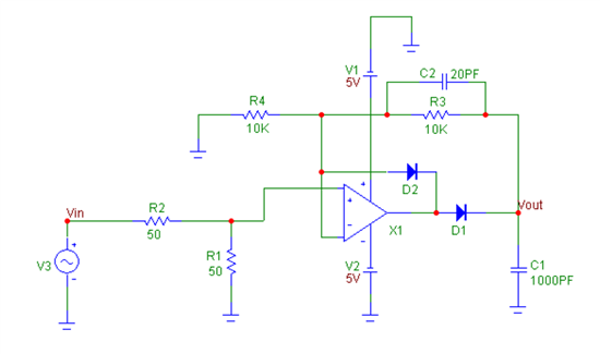
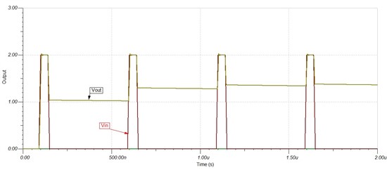
I also compared with an alternative schematic offered by the original poster:
And now are my questions finally:
1) The TI schematic in Fig. 48 looks a little strange to me, that is, the 300 ohm negative feedback resistor does not have another resistor to go to ground. Please see the alternative schematic, the R4. Why is that?
2) The 27pF capacitor in the TI schematic in Fig. 48 seem to be a little small. We found that with our proto board, the output just follows the input. I tried to increase it to 1nF and I see the output voltage starts to hold a bit. If I look at the alternative schematic, the charging capacitor is also 1000pF. So could this be explained?
3) When I increased the 27Pf to 1nF, the response time, both the rising and falling, gets bigger.
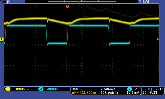
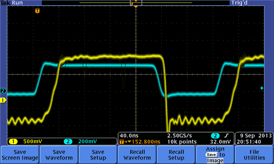
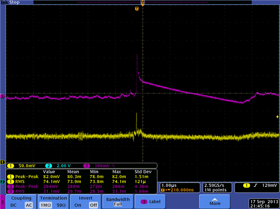
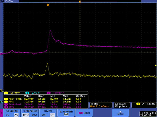
4) Anyway, I think my circuit has some problem. So here are the traces at pins #2 & #3 of the OPA615. The questins on these are:
a) the voltage relationship between #2 & #3 seem to be right, #3 (the base) should be about 0.7V above #2 (the emitter), correct?
b) what are the glitches and ringing in the traces? How do I get rid of them?
Thanks a lot,
Jay
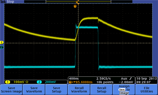
Pin #2 of OPA615 (channel #1, and channel #2 is the test signal from the sig generator):
Pin #3 of OPA615(channel #1, and channel #2 is the test signal from the sig generator):


