This thread has been locked.

If you have a related question, please click the "Ask a related question" button in the top right corner. The newly created question will be automatically linked to this question.

Op Amp Phase Shift

Other Parts Discussed in Thread: UAF42, TINA-TI

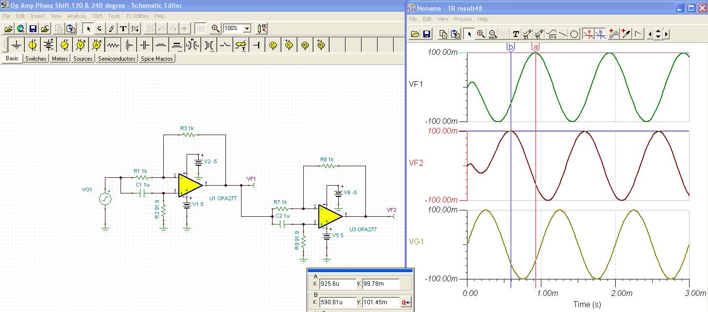
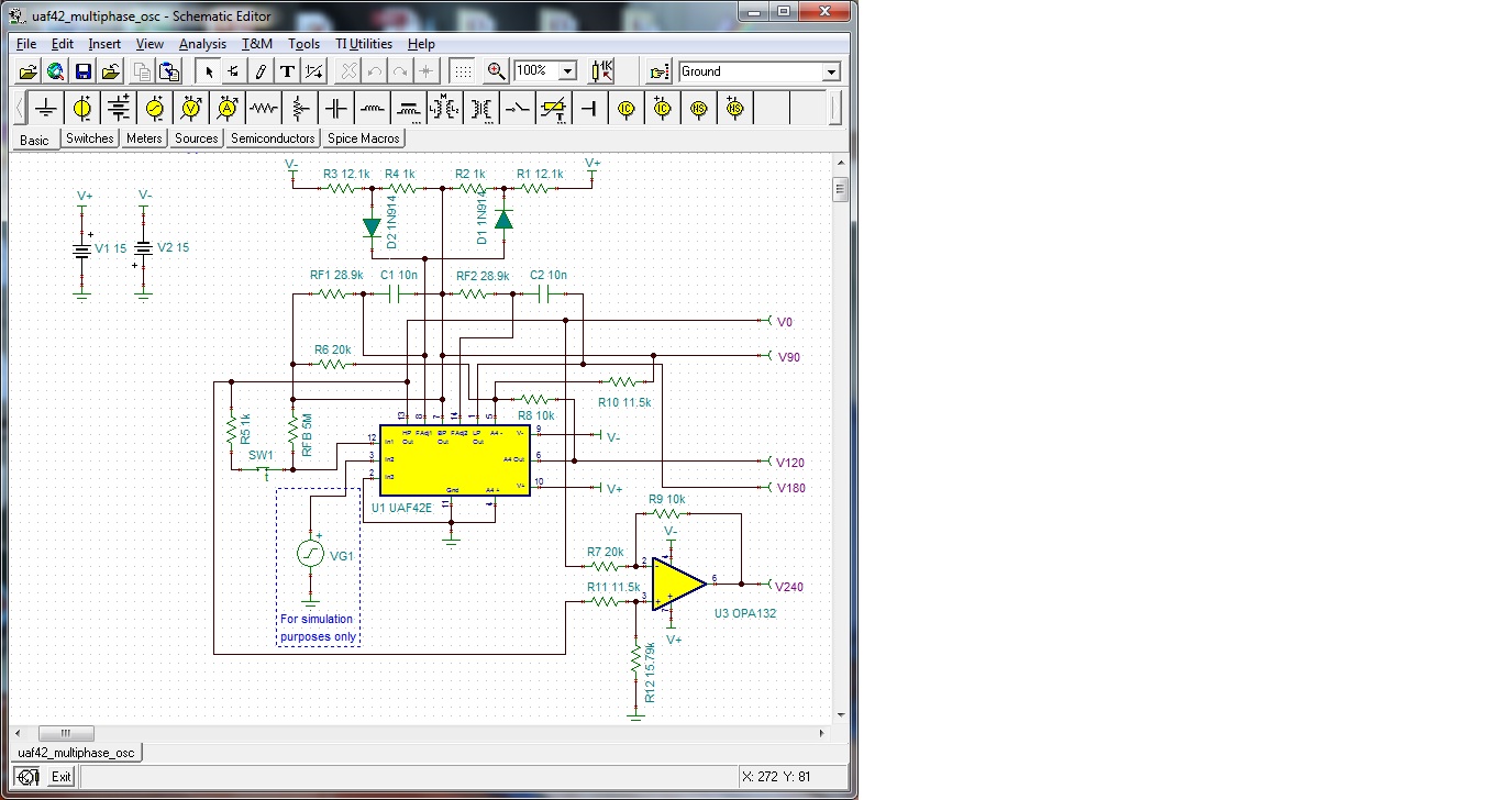
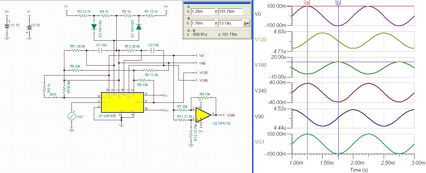
I have built the Multiphase Oscillator below based on the UAF42 and Application Bulletin SBFA013. My question is how do you derive/calculate the phase shift of 120 and 240 degrees? Is it due to the RC relationships for these particular phases?

  • Hi Greg,

    As we are not able to open an image you attached, it would be appreciated if you could send us a schematic in pdf, jpg, or gif fromat.

    If you would like to design 120 and 240 degree phase shift, I will recommend op-amps. The UAF42 has fixed connections which makes it uneasy to hook up for this purpose.

    Let me share an idea, which I have simulated in TINA-TI software. Signal frequency is 1KHz.

    For TINA-TI, I hope you will find easy to install from this site.

                http://www.ti.com/tool/tina-ti

    We do have a filter-pro, which supports phase shift circuit design. This will give you more accurate design.

                http://www.ti.com/tool/filterpro


    Best regards,

    Ichiro Itoi

  • Hi Ichiro,

    Thanks for your reply. Hopefully you will be able to view the JPG image of the UAF42 schematic configured as a multiphase oscillator.

    Regards,

    Greg

  • Hi Greg,

    Thank you for sending us a schematic. I guess you are going to make not only 120 and 240 degree phase but also 0, 90, and 180 degree phase.

    If so, UAF42 will be able to take 0, 90, 180, and 120 degree phase.

    I attached reproduced simulation result, which schematic is same as what you sent me. 

    7457.Op Amp Phase Shift UAF42E customer.TSC

    It seems some signals are attenuated. I wonder if there are any reason.

    Best regards,

    Ichiro Itoi