This thread has been locked.

If you have a related question, please click the "Ask a related question" button in the top right corner. The newly created question will be automatically linked to this question.

Quadrature Oscillator with TLV2474

Other Parts Discussed in Thread: TINA-TI, TLV2474, LMV344

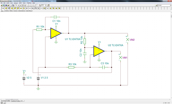
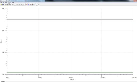
I am trying to simulate the schematic given in Application Report SLOA060 page 19, figure 20 with TINA-TI but I can't achieve oscillation at all.

This is the TINA-TI schematic I made:

And these are the results of a transient simulation:

I have just started using TINA-TI and would appreciate any help you could give.

  • Simon,

    V+ and ground are reversed on U1.

    Regards, Bruce.

  • Thanks for the quick reply!

    I was afraid it would be something stupid like that..

    But reversing the supply in fact doesn't get the circuit to oscillate either, it just raises the second output level to roughly  2.5V as well.

  • Simon,

    Can you please attach your TINA schematic file?  (.TSC file)

    Regards, Bruce.

  • Simon,

    I did some quick playing with the circuit. It is very close to sustaining oscillation. Changing R2 to 10.5k will cause it to sustain oscillation. The original authors of the note that you reference are no longer with TI so we cannot consult with them. Oscillators of this type can be tricky and there is a tradeoff between providing enough gain to oscillate and overloading into strong distortion. This circuit would probably require optimization with a nonlinear element to better control the feedback for reliable performance.

    Regards, Bruce.

  • You mean like the lamp in Hewlett's Wien Bridge Oscillator? I was actually hoping to get around something like this. Maybe a pot and a little fiddling with the tuning could make it work as well? I'll try to set this up with real elements some time soon and see if it works.

    Thank you very much in any case for your fast and thorough help, it is most appreciated!

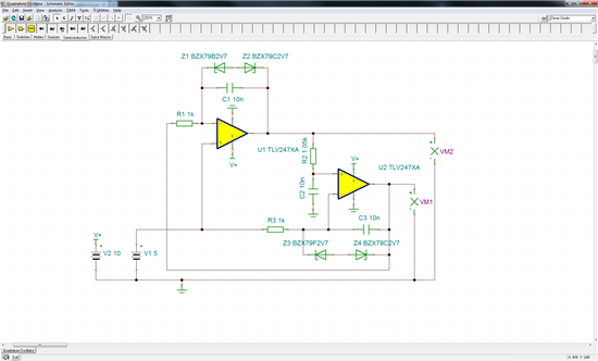
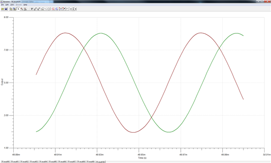
  • Sorry to reopen this thread, but I have been thinking about what you said about non-linear feedback and have placed two Zener diodes in the feedback loops of both amps. Without the diodes the output voltages run against the rails and clip but with them the output becomes a pure sine/cosine wave. However this does not work for 5 V supply which I assume is due to the breakdown voltages of the diodes.

    Here is the updated schematic (I also changed the frequency to 10 kHz because that's what I want in the end):

    1738.Quadrature Oscillator.TSC

    And these are the transient simulation results:

    I am posting this partly to share it with anyone who might want to do something similar in the future and partly to ask if anyone sees any pitfalls or redundancies I overlooked.

    So I'd be glad to get some feedback from anyone!

  • Hello, 


    I'm having trouble with this circuit. We're testing it for temperature independence and noticed the output waveform drops significantly when any heat or cold is applied.

    I replaced the LMV344IDR with TLV2474 and got better results in terms of temperature independence (voltage practically constant)
    I had to add the 150k resistor between pins 8-10 to get oscillations to trigger, however... I think it's kicking up the gain a tad and I'm getting clipping in my output waveform. 

    Is there any way to avoid this without putting in the diodes like you did before? You said it wouldn't work for a 5V supply, which is what I have. Let me know.

    Thanks,

    Pranit

  • HI Pranit,

    The LMV344 is NOT rail-to-rail input. The TLV2474 is a rail-to-rail input.

    Some of the (simulated) waveforms are within 800mV of the rails on the inputs on U700C, so they are encroaching on the common mode limit. This limit changes over temperature - so that is most likely what you are seeing.

    So you would need to reduce the amplitude, or, stick with the R-R input device.

    Regards,
  • Hi Paul,

    I am seeing the clipping in the R-R TLV2474s itself, I stopped using the LMV344 because of the temperature problem. 

    Got rid of the 150k and made the input resistor 8.5k to get the slight amount of gain for oscillations.

    Either way, I am now using this new circuit and I'm still getting some clipping, should I increase the 8.5k to 9.1k or something to reduce the gain?