This thread has been locked.

If you have a related question, please click the "Ask a related question" button in the top right corner. The newly created question will be automatically linked to this question.

LM321/LM324 for current sensing

Other Parts Discussed in Thread: LM321, LM324, TLV2401, INA193, LMP8645, LM358

Hi,

we need to amplify a 10mV to 100mV sense voltage developed over a shunt resistance on a 12V rail into a 3,3V range of an ADC. Precision is not of paramount importance and this being a low-volume project individual tuning is acceptable.

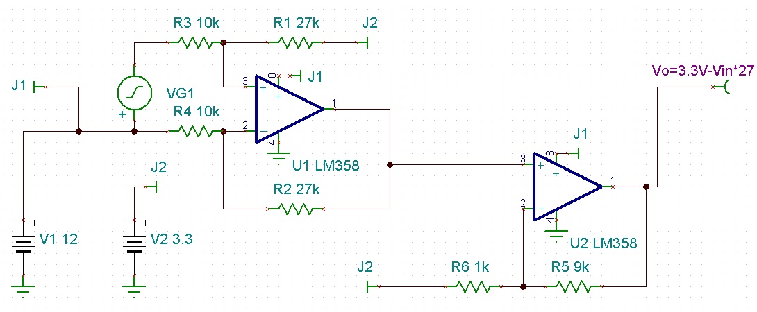
An obvious first though was using a OpAmp specified for up to12V supply voltage and configuring it as a differential amplifier with gain around 27. I am aware that the tolerances of the divider networks are of importance. Also, I assume that an instrumentation amplifier would probably be the better choice, but it is deemed to costly.

Now: most OpAmps are specified for their inputs to only slightly exceed their supply which means that I would need to power the device from the 12V rail, which however is not very well regulated. Also this would usually mean that the output could exceed the 3.3V limit of the ADC in case of very high current (and hence sense voltage). Then I found the LM321 which seemingly allows a full 32V on its inputs unrelated to the supply voltage. Is that really the case?

Put simply:

1. Does the LM321 function properly as a differential amplifier when powered by 3.3V and 12V on the inputs?
2. Are there other (cheaper) devices that do provide such functionality?
3. When powering from 12V rails is inevitable, how to safely limit the output to 3.3V possibly with another OpAmp?

Thanks

Arne

  • Hello Arne,

    Unfortunately, no. The LM321 is not an "Over the rails" type device. The "(V+) - 2V" common mode limit in the table still applies  - which means the input has to be at least 2V below V+. Going above that would pinch off the input stage current sources and the input stage would collapse.

    See note 9 on page 4. Note that "without damage" does not mean that it is still functioning. It just means that you won't break anything.

    The LM321 (and the rest of the older LM324/358 series) does not have ESD diodes on the inputs and has fairly rugged PNP input devices, so the inputs can go over the rails without damage, but the output state will be indeterminate.

    The TLV2401, 2402 & 2404 have "over the rails" inputs that can go 5V above the supply and still function. But that may not be enough for you...

    It sounds like what you really want is a "Current Shunt Monitor" amplifier, which is designed for exactly what you are trying to do. They have a power supply that is unrelated to common mode voltage, so you can safely power it from the 3.3V w/o damaging your ADC.

     http://www.ti.com/paramsearch/docs/parametricsearch.tsp?family=analog&familyId=426&uiTemplateId=NODE_STRY_PGE_T

    (Link corrected from original post)

    I know there are a scary amount of devices shown, but they boil down to a few basic devices. The "current" output type requires a resistor to "program" the gain, and the "voltage" output type usually has a fixed gain, and is more like what you would expect from an op-amp circuit.

    So to get your 100mV up to say 3V, you would need a gain of 30. The fixed gain sizes are 20, 25 and 50 (INA193/194/214/216), or you could use a "programmable" device (LMP8645) where a resistor sets the gain (dial in the exact gain you need).

    While the Current Sense chip may cost more than the op-amp, you eliminate all the resistors and save board space (and headaches).

    Hope this helps.

    Regards,

  • Arne,

    The LM321. LM358 & LM324 amplifiers have a common mode that is Ground to VCC-2V. It survives up to 30V.
    These amplifier have a very low sink current drive when Vout is less than 0.8V.

    I attached a circuit that provides a gain of 27 sensed from a 12V rail. (the gain of the first stage is low (2.7) to get a good input common mode voltage).
    The second stage give a gain of 10 for a total of 27. VG1 is the sense resistor voltage (minimum 0V and high maximum voltage) The output is 3.3V - VIN *27.
    This offset and inversion keeps the output in the 0V to 3.3V range.

  • Arne,

    Here is the TI-Tina model.

    The simulation was good, but I'd increase R5 and R6 to 20X the resistance, due the the weak sink when Vout is less than 0.8V.
    I would also add a resistor in series with the non-inverting input of the second amp Value=(R5*R6)/(R5+R6).

    Things like this are the headache Paul mentioned.

    LM358 3.3V limited Gain =27.TSC
  • Thanks a lot. Measuring from +3.3V downwards never occurred to me but it (now obviously) doesn't matter for later processing.

    I will breadboard the circuit with a single stage first to see if it suffices our needs.

    Best regards,

    Arne