This thread has been locked.

If you have a related question, please click the "Ask a related question" button in the top right corner. The newly created question will be automatically linked to this question.

Inverting Attenuation circuit output equation with solution

Other Parts Discussed in Thread: TINA-TI, TLC25L2

 Hi,

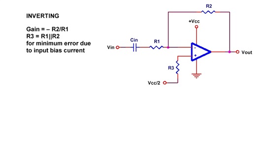
       I am unable to understand   "Inverting Attenuation circuit given SLOA058" , I tried with Orcad pspice , results were not matched. Please explain me the output equation and its steps. I want this attenuator for one of my application with TLC25L2 . explain me with some examples please. I tried with TINA-TI also. 

  • Raj,

    Could I suggest a different approach to your situation?  Please describe the circuit function you are trying to create. Please provide input voltage range, output voltage range, power supply voltage(s). What type of signal are you processing? Is it AC or DC? Frequency range? This information will help determine whether this is the correct circuit configuration.

    Regards, Bruce

  • Raj,

    I looked further at the application note that you referenced and the circuit diagram in your original question. This circuit is unnecessarily complex. The circuit diagram shown in figure 4 of the application note can more easily implement the same circuit function and is stable with unity-gain stable op amps. The comments in this application note are incorrect and lead to a circuit that is more complex than is required.

    Regards, Bruce.

  • Mr.Bruce

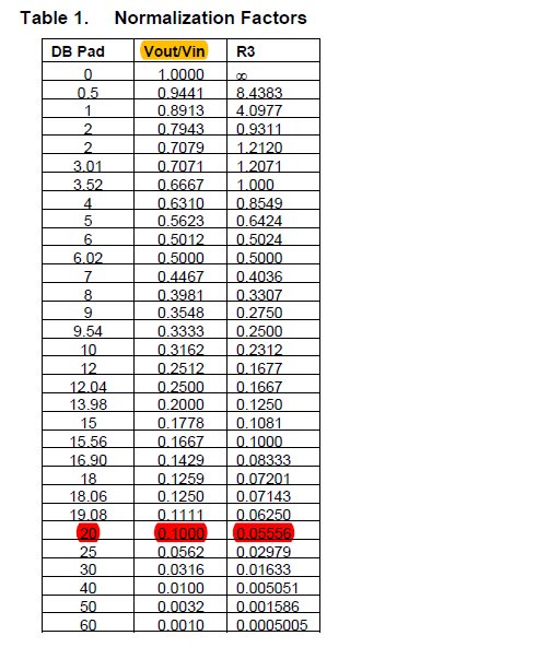
                     My requirement is attenuating dc-voltage levels  from   0v - 3v to 0.1v - 0.3v . I had studied the document "SLOA058" and happily chosen the TLC25L2 Precision Instrumentation Amplifier. Later, I start simulate with ORCAD 10.3 PSPICE and TINA-TI ,  tried hard, expected result has not arrived. GIven Table.1 normalization Factors and R3 = (V0/Vin)/2-2(V0-Vin), not worked out for me. 

                  Single supply inverting op-amp circuit   simulation

    Single supply inverting op-amp circuit simulation is not even given me the expected inverting amplifier output . How to work with inverting amp with single supply mode. 

    I had bought TLC25L2 100 Nos, once schematic ready and confirmed then I would start production.

    Please suggest me an inverting attenuator op-amp circuit with stable operation for dc signal input and instrumentation application.

    Thanks in Advance ,

    raj 

  • Raj,

    Please let me understand fully. Your description,  0v - 3v to 0.1v - 0.3v, does not appear to be an inverting circuit, but is non-inverting. In your desired circuit does 0V input correspond to 0.1V output?  And does 3V input corresponds to 0.3V output?

    Regards, Bruce.

  • Mr.Bruce 

                   yes Mr.bruce, You are right but small correction, Vout/Vin ratio is 0.1.  I thought  the inverting attenuation will work at single supply mode for positive output as per document SLOA058 by feeding VCC/2 to non-inverting terminal.  Even,as per SLOA058 the simple inverting amplifier circuit also takes VCC/2 in non-inverting terminal and gives positive output, for this clarification only I have pasted a simple inverting amplifier image in previous reply. 

            here i just tabulated my requirement as Vout/Vin ratio 0.1. Please explain me the inverting attenuation will work for me if not then suggest alternate schematic with an image.

                  Input            Output

                   0                     0

                    0.1                0.01

                   0.2                 0.02

                    -                       -

                    -                      -

                   1                       0.1

                   1.1                    0.11

                     -                      -

                    -                       -

                  2                        0.2

                2.1                       0.21

                2.2                       0.22

                 -                            -

                3                           0.3


    Thanks in Advance


    raj

  • Raj,

    The transfer function you describe in this latest post is a simple non-inverting attenuator. An inverting attenuator would have an output voltage that moves in the opposite direction in response to an input voltage change.

    A simple two-resistor voltage divider with a 9:1 ratio divides the input signal by 10 (gain of 0.1). The op amp is required if a low output impedance is required. The op amp will not be able to swing fully to 0V without a negative power supply on the op amp. How close it will come to 0V will depend on load conditions.

    Regards, Bruce.

  • Mr.Bruce

         As per your comment ,Inverting attenuator would not fit to my requirement . I just followed the document SLOA058 and listed table of value  for R3 resistor for the inverting attenuation circuit . Please let me the output transfer function for the inverting attenuator and also explain in detail  about "A Single-Supply Op-Amp Circuit Collection" document mentioned simple inverting  amplifier circuit (Figure.3 in page number .6) with output transfer function, if possible simulated images.

    Please suggest me some other techniques for attenuation of 0.1 (Vout/Vin = 0.1) Resistor T- network in input and/or in feed back path with transfer function.

    schematic 

    Thanks in Advance,

    raj

  • Raj,

    The circuit diagram in my previous post provides your desired transfer function.

    I suggest that you not try to use SLOA058 document. It contains too many errors.

    Regards, Bruce

  • Mr.BRUCE

                          Please suggest me that single supply inverting amplifier is possible or not. If possible explain me with clear transfer function and simulated image. The document SLOA058 says all about "SINGLE SUPPLY OP-AMP APPLICATIONS", i just want corrected document as early as possible with detailed explanation. Partial information may introduce errors as did in SLOA058. Give solutions after simulation or testing.

    Thanks

  • Raj,

    Here is the design of a single supply inverting attenuator:

    Regards, Bruce