


Hello,
I am designing a 4 channel ADC/DAC frontend which uses the following chips
- ADC: http://www.ti.com/product/ads8331
- DAC: http://www.analog.com/en/digital-to-analog-converters/da-converters/ad5686/products/product.html
Both of these chips convert/generate signals in the range of 0 to VRef. However, my device needs to convert/generate bipolar signals from -Vref to Vref. To do this, I am using the OPA365 to level-shift and amplify input and output voltages into the appropriate range. Below I have pasted the circuit designs I am using to do this:
DAC Buffer (non-inverting 2X gain with -Vref level shift. DAC_A+ signal is coming directly from the output pin of the DAC. VREF is 4.096 volts and coming from the REF5040) :

ADC Buffer (inverting 0.5X gain with +Vbias=Vref/2 level shift) :

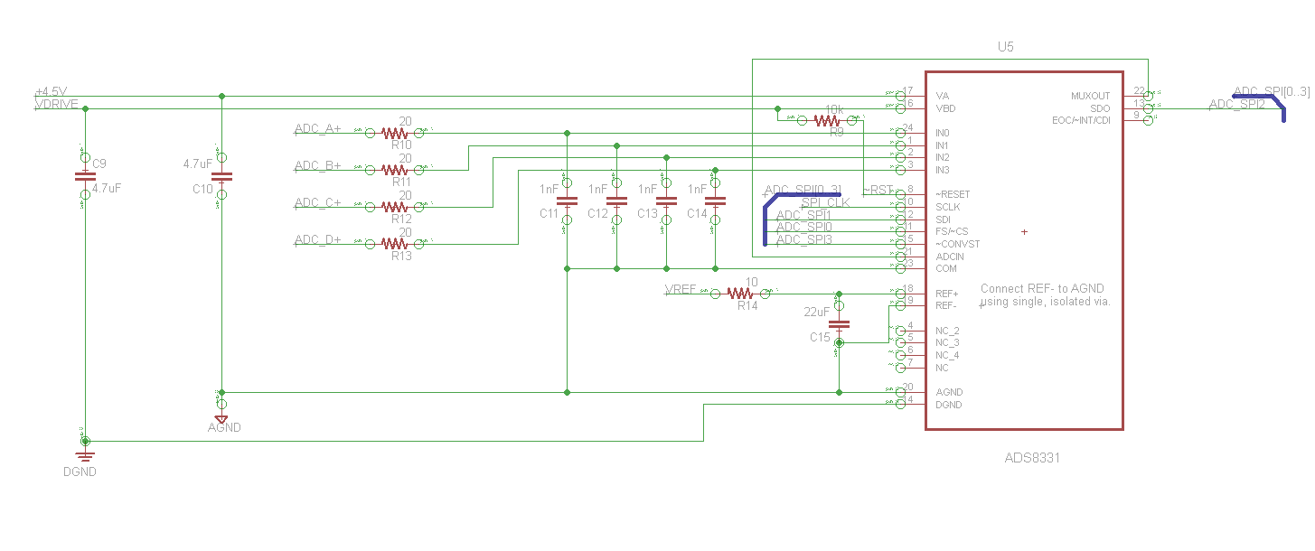
The input stage for the ADC is pictured below:
My problem is that after the signals have passed through these op-amps (at the ADC input stage or the final DAC output stage), they have both incurred have a ~10 MHz, ~40 mVP2P oscillation. Here are some oscilloscope shots (10X probe, properly compensated) . I have labeled each trace to correspond to the circuit diagrams above.
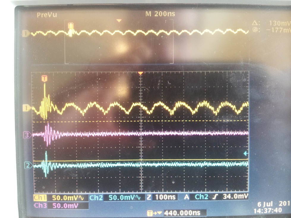
DAC Output buffer. Yellow: DAC_A, Pink: DAC_A+, Blue: Positive supply rail. Please ignore the large, high frequency transient that appears in all three traces. This is the result of a switching power supply that has since been removed from the circuit. I interested in the periodic signal on the DAC_A line.
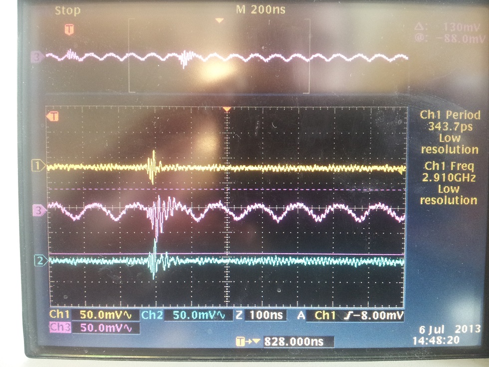
ADC Input buffer. Yellow: ADC_A, Pink: ADC_A+, Blue: Positive supply rail. Please ignore the large, high frequency transient that appears in all three traces. This is the result of a switching power supply that has since been removed from the circuit. I interested in the periodic signal on the ADC_A+ line.
I will mention that each chip derives power from a +/- 4.5 Volt LDO regulator pair.
I will also mention that I have tried the circuit both on a PCB in which i did my best to observe proper layout procedures and on a breadboard, and both situations show this oscillation. My questions are the following:
1. What could be causing this oscillation?
2. Am I using the right op-amps for these applications? I have begun to wonder if an op-amp with better capacitive drive capability would be a better choice for the DAC output driver
3. Any recommendations for different IC's and topologies to accomplish my goal would be much appreciated.
Thanks.
- Jon

