This thread has been locked.

If you have a related question, please click the "Ask a related question" button in the top right corner. The newly created question will be automatically linked to this question.

Driven Right Leg circuit questions

Other Parts Discussed in Thread: INA326

Hi


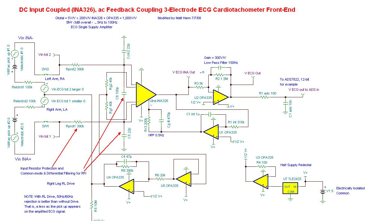
This question is about Driven Right Leg (DRL). I found that the DC level of DRL signal, see below, from INA326 is not exactly 1/2V+. This makes the DRL circuit to be saturated.


Do you guys have any solution for improvement or avoid this."


Questions:

1. Can I use a capacitor with a large value, say 10uF, in between U4 and U5, to block the DC so that U4 will not be saturated? Will this make the DRL circuit have no 60Hz cancellation? I have tried it and it looked good. I could a 60Hz square wave at the output of U4. 

2. How can I fine tune the the DRL circuit to make it has the best cancellation effect? I think I need to adjust the gain of U4 to achieve maximum cancellation.


Thank you very much


Xijun

  • Xijen,

    You mean you want to AC couple the output of the RL drive?  You should be careful about this as the entire circuit derives its common mode voltage from the RL drive and the inverted noise voltage ideally rides on VCM.  If you hook up a mid supply DC reference voltage (in place of the RLD) to your simulated ECG inputs do you get a valid output at the INA326?  Start here  and debug this first--then move on the RL drive and figure out why it is saturating.

    If everything else in the circuit works, consider that your gain in your RLD circuit is limited by the worst case offset you expect from the electrodes.  So if you expect a 300mV electrode offset and VCM is 2.5V, Vin+ = 2.8V and Vin- = 2.5V, so the average voltage fed to the RLD circuit is Vavg = (Vin(+) + Vin-) / 2  = 2.65V.  So on your RLD circuit if Vref = 2.5V this means that your gain should be limited to GND < Vref + (Vref - Vcm)*G = Vout < VCC.  The other thing to consider is that you may very well have to compensate the RLD amplifier based on the gain that you choose to keep it stable.

    Matt

  • Hi Matt 


    Many thanks for your quick response. Please see my replies with ">>"


    You mean you want to AC couple the output of the RL drive?  

    >> Yes. I want to AC couple the RL drive signal at the input of U4 (before R6), see above circuit.


    You should be careful about this as the entire circuit derives its common mode voltage from the RL drive and the inverted noise voltage ideally rides on VCM.

    >> What does VCM stand for? I do not standard this one. I would appreciate it if you could further explain. Thanks!


    If you hook up a mid supply DC reference voltage (in place of the RLD) to your simulated ECG inputs do you get a valid output at the INA326?

    >> I can desired output signals (or valid output) at the INA326. Its gain is okay. DC level is about 1/2V+. Frequency response curve is okay too.


    Start here  and debug this first--then move on the RL drive and figure out why it is saturating.

    >> The problem is that the DC level at the output of U5 is about 1.2~1.5V (I cannot remember the exact value). Referring to your reference circuit, the gain of U4 is about 20. So, the output of U4 is always V+ (saturated)


    The other thing to consider is that you may very well have to compensate the RLD amplifier based on the gain that you choose to keep it stable.

    >> Sorry, I do not really understand this one too. I would appreciate it if you could further explain. Thanks!


    Questions: 

    1. What DC voltage do you expect at the output of U5? It should be 1/2V+, shouldn't it?