This thread has been locked.

If you have a related question, please click the "Ask a related question" button in the top right corner. The newly created question will be automatically linked to this question.

UC1843: output does not switch

Part Number: UC1843
Other Parts Discussed in Thread: UCC28C43, ,

Hi everybody,

I'd like to design a rad-hard non-isolated DC-DC boost converter using the TI UC1843 PWM controller to increase the voltage of a solar panel.

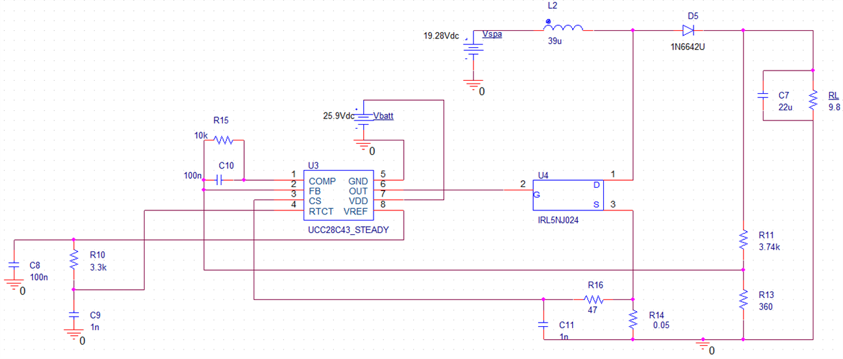
I've performed some simulations with PSpice before implementation and I've came up with the attached design. However, after I've mounted the circuit on a breadboard, only the oscillator seems to work. The output doesn't switch even if I disconnect everything and leave only R10, C9, C8 and connect FB and CS to GND.

What I'm doing wrong? Am I missing something?

Thanks in advance,

NT

  • Hi Nicola,

    Are you using UCC28C43 or UC1843 for your design. as the schematic shows UCC28C43.
    You may want to add a localized capacitor close Vdd to gnd, also make sure that your compensation components, oscillator components are mounted close to the IC. Capacitor across the Vref should be mounted close to the IC ensure reference stability, use min capacitance of 0.1uf or higher possibly 1uf close to the pin.
    Keep in mind as UC1843 is a current mode control thus layout is a critical part of the equation.
    Have you monitored other pins i.e. Vref and you are getting the appropriate voltage there.
    You can also configure the IC in open loop to check the IC as shown on pg. 8 of UC1843-SP & monitor waveforms.
  • Hi Ramesh,

    thanks you for the reply!

    I am using UC1843. The schematic shows UCC28C43 because that is the pspice model which I had found on the UC1843 page.

    I have mounted all the components as close as possible to the IC, and Vref and COMP gives the expected voltage. I have also mounted the open loop configuration as you suggested, however it still does not work and the output is stuck at GND. The only signal that I can see is the one on RTCT pin, which oscillates at the right frequency.

    Do you have some other ideas?

  • Hi Nicola,

    Can you take scope shots of wave forms on each pin on your circuit. I will correspond off-line via email to help your issue.