This thread has been locked.

If you have a related question, please click the "Ask a related question" button in the top right corner. The newly created question will be automatically linked to this question.

AFE4300: AFE4300

Part Number: AFE4300

Dears

      when customer use the AFE430EVM for debuging and their own designing, they find that some of the register write a value, and then reading it , the value changed. such as below example. pls. help to give the reason. thx


  • Hi Aggil,

    Is the customer seeing this behavior in the AFE4300EVM as well? Or are they noticing this SPI issue on their custom board only?

    Based on the data the customer is writing, it seems like the least significant bit is either incorrectly getting written to or being read from.
    Please check the SPI timing interface on their board.
    The device latches data on SDIN on the falling edge of SCLK. Data is shifted out on SDOUT pin on the rising edge of SCLK.
  • Hi Praveen

       Both on the EVM  and custom board are all the same .

       Another,  customer find new question , pls help to check .

    When read the value  IQ of 14 channells, it find that the value of IQ happen to saltus step. After this , the IQ have another rule. This example as below :

  • Hi Aggil,

    Can you please re-post the image with the comments in English?
    Also please elaborate the question.

    Regards,
    Prabin
  • Hi 

      When I set the same mode(same MCLK, same frequency-division), the IQ have different rule. 

      My question is this phenomenon is normal? and what make this this phenomenon happen?

    This example as below :


    Best Regards

  • Hi Weiteng,

    The phenomenon you are observing is normal. The reason for this behavior is change in the register settings that control the DAC frequency (i.e. BCM_DAC_FREQ) and the division factor for IQ DEMOD (i.e. IQ_DEMOD_CLK). Whenever you change these two register, the block responsible for generating DAC frequency and IQ_DEMOD CLK gets re-initialized. Also the phase relation between the DAC output and the I-Q demod clock can get altered.

    The fix for this phenomenon is to do calibration every time you change the BCM_DAC_FREQ or IQ_DEMOD_CLK as seen in your results as the magnitude remains same for each case.

    Regards,
    Prabin
  • Hi 

      Thank you for your patience.

      I have another question is that  when I the IQ rules changes(same MCLK, same frequency-division), I will do calibration and calculate other channels impedance, but

    calculated impedance have a little difference between different IQ rules. Some IQ rules, the difference are big.

      Can you provide a calibration algorithm, Thank.

    Best Regards

  • Hi Weiteng,

    Can you please share the data (along with their IQ rules) with bigger difference?

    Regards,
    Prabin
  • Hi Prabin

    This example as below :

    Can you provide a calibration algorithm, Thank.

    Best Regards

  • Hi Weiteng,

    Here is the simple calibration algorithm.

    1.  Pass the same excitation current through two known impedance and measure the voltage developed across it.
      1. i.e. Y1 = MX1 + C and  Y2 = MX2 + C , where X1, X2 are the two known impedance and Y1, Y2 are voltages across them respectively. M = Excitation current, C = Offset.
    2. Find the Current and offset by using values from Step 1.
    3. Measure the voltage across the unknown impedance.
    4. Calculate the unknown impedance by subtracting offset from voltage ( from step 3) and finally divide by current.

    After implementing this algorithm can you please share values following for each IQ rules

    1. Values of Calibration impedance
    2. Voltages across calibration impedance ( I and Q)
    3. Voltage across unknown impedance  (I and Q)

    Regards,

    Prabin

  • Hi Prabin
    1. I'm not sure if my algorithm is correct. In my algorithm model:
    a. impedance _modulus = a * sqrt(I^2+Q^2) + b (a & b use four known impedance to calculate)
    b. impedance _phase = atan(Q/I) - c (c use four known impedance to calculate)
    *The data use my algorithm model as above. And my four known impedance value is (96.35, 187.54, 567.62, 691.62).

    2.In your algorithm( Y = MX + C), Is it just about the calibration of the modulus of resistance? And what about phase.
    It seem that our algorithm about modulus is same.

    3.Please help me to analysis why unknown impedance have bigger difference in different IQ rule. Thank you very much.

    Best Regards

  • Hi Weiteng,

    Basically we have same algorithm, even for my case you can find phase from calibration resistors and subtract it from unknown resistors's phase. 

    To understand your data can you please tell me why the I/Q values are changing as shown below ( marked in RED)?
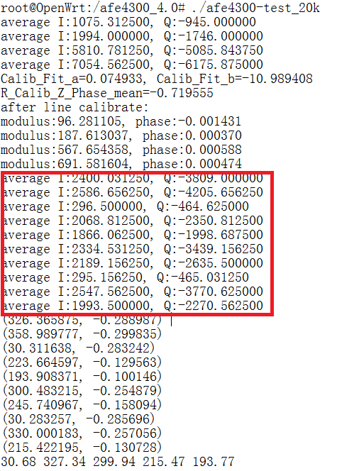
    Is it for different IQ rules, if yes share the BCM frequency (as well as IQ Demod frequency) for each of those.

    Can you also measure the voltage across the unknown resistors using the oscilloscope? For different IQ rules, the frequency will change but swing should be same.

    Regards,

    Prabin

  • Hi Prabin,
    As the spec, the Excitation current is 375 µArms, and with a +20% error. Is the work of calibration current to fix 20% error? If it is only for fix 20% error . Can we only do the calibration process by the first time? And the later don't to calibrate again?
  • Hi Lin,

    Since the same excitation current flows through the calibration resistors and the body, the knowledge of current's absolute magnitude is not important. Doing calibration you remove all the variable which may come from 20% variation in R1 , variation due to parasitics, etc. Since these variable changes with the operating conditions its advised to do calibration every time the operating condition is changed.

    Regards,
    Prabin