This thread has been locked.

If you have a related question, please click the "Ask a related question" button in the top right corner. The newly created question will be automatically linked to this question.

DRV8308: motor driver behavior when switching direction / DIR

Part Number: DRV8308

Hello there,

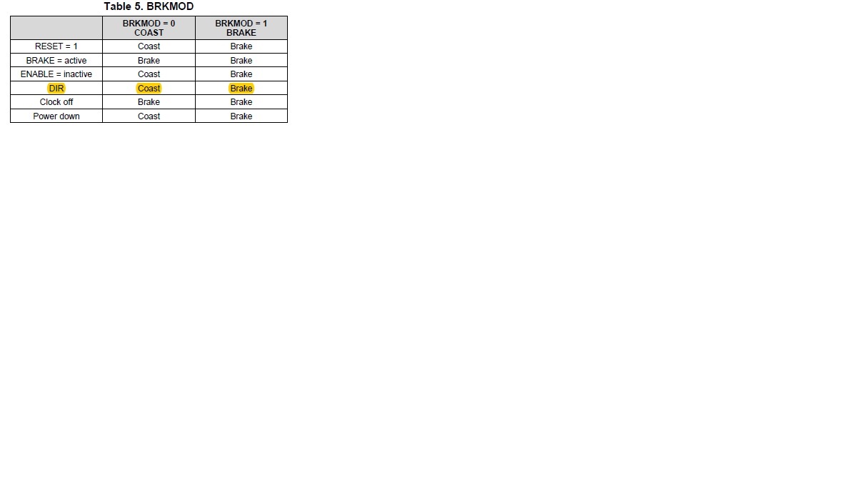
My application requires to change motor rotate direction.  I am wondering what DRV8308's behavior during this transition period with BRKMOD = 1.  On data sheet (Table 5 as I copied in the following), it simply says DIR, brake.  My understand is: when DIR switches, i.e either from high to low or low to high, driver chip will switch into BRAKE mode.  However when it is the condition for the driver chip starts to drive normally.

for example, I run the open loop with pwm duty cycle is set to 10% and motor rotates (BRKMOD =1, brake PIN is not set during the test run).   Then I switch the DIR pin to reverse the direction.  When or under what conditions that 10% duty cycle applies to motor and motor starts to reverse the direction?    somehow I saw a noticeable amount of time that motor being stopped before it reverses rotation. 

thanks,

Hong

  • Hi Hong,

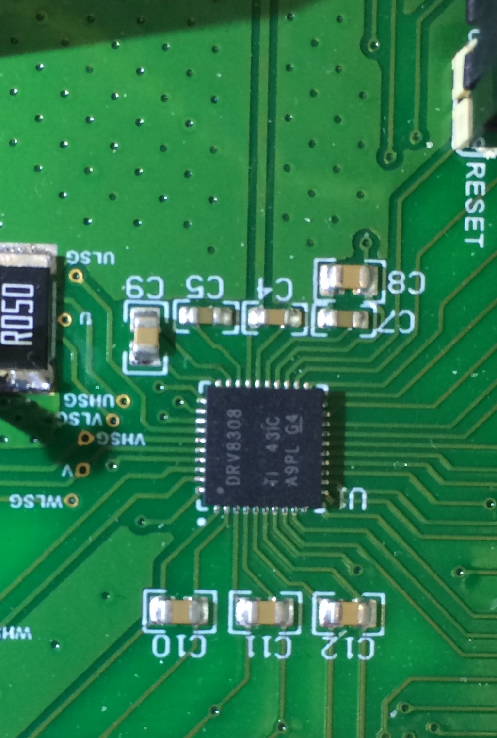
    Can you provide either the markings on the top of the package or a picture of the device?
    We would like to determine if you have material that matches revision A or B of the datasheet.
    Once we have this information, we will reply.
  • Hello Rick,

    I think we have version A as I saw the RLOCK fault is set in fault register.  Anyway, please see the image of chip.

    I am in the stage to decide to buy a batch of DRV8308 chips and how can I ensure that I get the version B instead  of A?

    thanks,

    Hong

  • Hello Hong,

    If you buy from our TIstore, you should get version B of the device. Let me confirm this and will get back to you by tomorrow. Thank you.
  • thanks. What about my initial question of motor behavior during rotation direction change?

    best Regards,

    Hong
  • Hi Hong,

    The direction of the motor is controlled through the DIR pin.
    The BRKMOD bit only changes the how the motor stops. Depending on the ENABLE pin, BRKMOD brakes the motor by turning on the low side FETs or by coasting through the FETs' diodes. If BRKMOD is set to coast mode, yes, it will take more time.
    Thank you.
  • what is the behavior during switching the DIR pin: PWM duty cycle continue applies to the FET while DIR transit from low to high or high to low?   So my questions are:

    1) I clearly observed motor stop during switching direction and then some delay later, it starts to reverse the direction.   Is that expected behavior or abnormal behavior for DRV8308?     

    2) And as you explained BRKMOD only control motor stops, what does it mean when the data sheet of DRV8308 put DIR in the table 5?   

    3) I was asked about which version of the chip I have, rev a or b.   So I am expecting the behavior difference between these two .  Could you please confirm that my chip is rev a. based on the image I posted based on the request?  And I do plan to buy rev b chip, could you please explain the difference between these two revision of chips when switching the direction with BRKMOD=1.   

    thanks,

    Hong

  • please see my reply to this post. Sorry I didn't know I could enter text here to indicate I need further explanation to my initial question.
  • Hello Rick,
    I have provided the picture of the chip. Is that what you need? what is the expected behavior for both rev a and b chip when DIR flips with BRKMOD = 1?

    thanks,

    Hong
  • Hello Hong,

    For question #1: Yes, this is expected as current cannot change instantaneously and there will be some time to transition between directions.

    For question #2: Table 5 shows how BRKMOD affect the mentioned inputs. The Direction (DIR) in this case is a don't care condition, whatever the DIR voltage level on that pin is, will just follow the BRKMOD setting. For BRKMOD=0 the motor will COAST regardless of what direction the motor is spinning. Same is true for BRKMOD=1.

    For question #3:  BRAKE can affect RLOCK which is not available in rev B. The complete change from Rev A to Rev B is stated in section 4 of the datasheet. You can also do a Google search for the rev A datasheet, please search: slvscf7a  to obtain the  details for rev A operation.

    For extra question: If you buy directly from the TI store, those parts are guaranteed to be rev. B. We cannot guarantee this if you obtain parts outside TI through a distributor.

    I hope this answers all you questions, thank you.

  • On "For question #1: Yes, this is expected as current cannot change instantaneously and there will be some time to transition between directions."   I understand that motor will overshot , stop and reversed back.  But do we expect that it overshot, slowed down, and then stopped for hundreds of ms before reverse direction?  Or let me ask it another way: when DIR change direction, PWM output to motor coil will change commutation direction right away (within a couple of clock cycles) with the amplitude I set to through either input PWM line or PWM register (open loop mode) instead of being smart and adding some other logic before applying the PWM output to the motor coils.     

    thanks,

    Hong

  • Hello Hong,

    I apologize as I don't understand your last statement. Maybe it some diagrams and/or scope captures of what you are seeing can better explain the situation. Could you please provide such... Thank you.
  • Hello Luis,

    thanks for your reply.  my setup is not available this week but I will provide the waveform as soon as my setup is available next week.

    thanks,

    Hong 

  • Hello Luis,

    sorry for the delay.  Here is the picture of voltage on V of the UVW PWM output when direction change is requested (PWM duty cycle is fixed by simply clicking direction button on TI UI to drive the evaluation board).  Through monitor encoder reading on motor shaft using another program, we can see that motor slowed down to a full stop and then stop for about 100ms then start to rotate again.   we choose 180 deg commutation, is the zero output of V signal is expected during direction change.  Note D/R is direction signal, Clkin is CLKin signal, and V is the V output.  time scale is 200ms/grid.

    thanks,

    Hong