This thread has been locked.

If you have a related question, please click the "Ask a related question" button in the top right corner. The newly created question will be automatically linked to this question.

PCM1862: PCM1862 audio

Part Number: PCM1862

Hello,

my questions is related to the 'wake up' sequence in the PCM1862. We have configured the IC to sample data at 16KHz with 16bits.

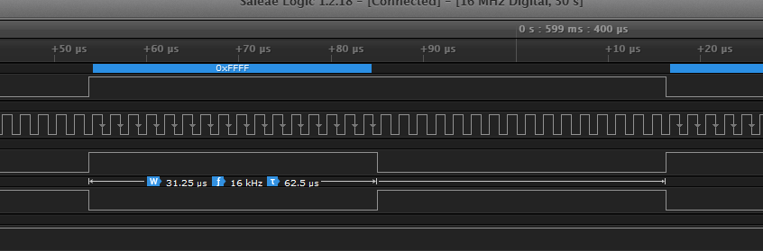
The resulted output stream is:

BCK 512Kz

LRCK 16KHz

But we have observed that just at the beginning , the PCM Output is unstable until it really locks at the configured Clock settings. This 'waking up' is unpredictable and sometimes 'damages' the receptor of the stream in the sense that it cannot synchronize with the PCM since it is setup to receive the stream clocks exactly yo 512KHz and 16KHz:

Here I attach a capture as an example:

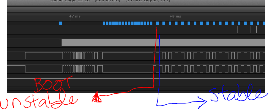
We wonder whether there is or not some boot sequence in the Config routine to ensure that the PCM does not releases any data until the clocks really lock to the expected Clocks configureation. Or maybe there is some way to put the PCM in some 'sleep' mode for some period and then wake it up in such manner that the output is really in the expected clocks configuration (as in the stable zone)

  • Alberto,

    Would you mind providing some more details? Do you have the PCM1862 running off of a crystal? or an external MCLK?

    what is your wake up sequence?

    best regards
    -Steve Wilson
  • Hi Alberto,
    What is your typical start-up sequence on your system?

    The device has normal power up sequence where it should go through POR, make sure Analog and Digital supply rails are stable/good, Internal oscillator is good before releasing the digital reset pin. Following this, we make sure PLL is stable and LOCKED (typically requires ~250uS) and then the digital modules start getting clocked and then the DOUT is driven.

    Can you please explain how your start up sequence is and whether you are configuring the device in auto mode or manually configuring the PLL etc.?

    Thanks.

    Best regards,
    Ravi
  • Hi Steve,
      we are using an external Clock that feeds the SCKI pin
      This is our sequence of SPI commands to configure the PCM. The format is (Register_address, VAlue)
      Sorry for trhe poor explanation about the meaning of the registers and values, I'm not an expert in it and besides I inherited the code from a former
      development

      Qspi_WriteCmdBuild(0x00, 0xFE); // Reset
      Qspi_WriteCmdBuild(0x0, 0x00); // select page 0 again
      Qspi_WriteCmdBuild(0x70, 0x14);
      Qspi_WriteCmdBuild(0x0, 0x03); // Select Page 3
      Qspi_WriteCmdBuild(0x12, 0x41); // Disable OSC
      Qspi_WriteCmdBuild(0x0, 0x00); // select page 0 again
      Qspi_WriteCmdBuild(0x70, 0x70);
      Qspi_WriteCmdBuild(0x0, 0x03); // Select Page 3
      Qspi_WriteCmdBuild(0x12, 0x00); // Enable OSC
      Qspi_WriteCmdBuild(0x0, 0x00); // select page 0 again

      Qspi_WriteCmdBuild(0x6, 0x50);
      Qspi_WriteCmdBuild(0xB, 0x4D);
      Qspi_WriteCmdBuild(0x20, 0x7E);
      Qspi_WriteCmdBuild(0x29, 0x00);
      Qspi_WriteCmdBuild(0x2A, 0x00);
      Qspi_WriteCmdBuild(0x2B, 0x04);
      Qspi_WriteCmdBuild(0x2C, 0xC0);
      Qspi_WriteCmdBuild(0x2D, 0x23);
      Qspi_WriteCmdBuild(0x28, 0x01);
      Qspi_WriteCmdBuild(0x21, 0x17);
      Qspi_WriteCmdBuild(0x22, 0x17);
      Qspi_WriteCmdBuild(0x25, 0x17);
      Qspi_WriteCmdBuild(0x26, 0x07);
      Qspi_WriteCmdBuild(0x27, 0x1F);
      Qspi_WriteCmdBuild(0x23, 0x2F);   >> -Here starts the PCM output
    Thanks for the help
     
  • Hi RAvi,
    we are using an external Clock that feeds the SCKI pin
    This is our sequence of SPI commands to configure the PCM. The format is (Register_address, VAlue)
    Sorry for trhe poor explanation about the meaning of the registers and values, I'm not an expert in it and besides I inherited the code from a former
    development

    Qspi_WriteCmdBuild(0x00, 0xFE); // Reset
    Qspi_WriteCmdBuild(0x0, 0x00); // select page 0 again
    Qspi_WriteCmdBuild(0x70, 0x14);
    Qspi_WriteCmdBuild(0x0, 0x03); // Select Page 3
    Qspi_WriteCmdBuild(0x12, 0x41); // Disable OSC
    Qspi_WriteCmdBuild(0x0, 0x00); // select page 0 again
    Qspi_WriteCmdBuild(0x70, 0x70);
    Qspi_WriteCmdBuild(0x0, 0x03); // Select Page 3
    Qspi_WriteCmdBuild(0x12, 0x00); // Enable OSC
    Qspi_WriteCmdBuild(0x0, 0x00); // select page 0 again

    Qspi_WriteCmdBuild(0x6, 0x50);
    Qspi_WriteCmdBuild(0xB, 0x4D);
    Qspi_WriteCmdBuild(0x20, 0x7E);
    Qspi_WriteCmdBuild(0x29, 0x00);
    Qspi_WriteCmdBuild(0x2A, 0x00);
    Qspi_WriteCmdBuild(0x2B, 0x04);
    Qspi_WriteCmdBuild(0x2C, 0xC0);
    Qspi_WriteCmdBuild(0x2D, 0x23);
    Qspi_WriteCmdBuild(0x28, 0x01);
    Qspi_WriteCmdBuild(0x21, 0x17);
    Qspi_WriteCmdBuild(0x22, 0x17);
    Qspi_WriteCmdBuild(0x25, 0x17);
    Qspi_WriteCmdBuild(0x26, 0x07);
    Qspi_WriteCmdBuild(0x27, 0x1F);
    Qspi_WriteCmdBuild(0x23, 0x2F); >> -Here starts the PCM output


    Thanks for the help
  • Alberto.  

    Are you following the sequence below:

    before you enable the BCL/WCLK ouptuts, you should be waiting for the PLL lock flag.

    best regards,

    -Steve Wilson

  • Alberto,
    You can also try to configure the part in AUTOCONFIG mode to run the device in MASTER mode at 192kHz sampling rate using the below script -
    w 94 20 17
    w 94 25 0F
    w 94 26 01
    w 94 27 3F
    w 94 28 11
    w 94 29 03

    I just ran this script on my bench and made sure the PLL is locked. This should resolve the problem in addition to the comments that Steve just posted. Thanks.

    Best regards,
    Ravi