This thread has been locked.

If you have a related question, please click the "Ask a related question" button in the top right corner. The newly created question will be automatically linked to this question.

TLV320AIC3204 SECONDARY I2S PORT

Other Parts Discussed in Thread: TLV320AIC3204

Hello,

On my TLV320AIC3204, I am using the primary audio port with BCLK (PIN 2) set as input and receiving a 128kHz 50% duty PWM from an MCU. In return, the WCLK (PIN 3) outputs an 8kHz 50% duty PWM along with 8-bit audio on DOUT (PIN 5) to that MCU.

Internally on the CODEC, I route MIC 1 (IN1L and CM1L) to the left MIC PGA channel like this:

P1_R52_0b01000000
P1_R54_0b01000000

The result is that the audio from my microphone is converted to an 8-bit digitized audio stream and that's perfect.

Now, the CODEC has a SECONDARY I2S port and it turns-out I have a second audio device. This device is generating both clocks and expects to receive digitized audio.

My MCU configures all CODEC registers through I2C, not SPI. I think I cannot use secondary I2S if I am using SPI. So this is not an issue.

IMPORTANT NOTE: I will be using only ONE audio device at a time. So on occasions, I will stream to DOUT 1, on other occasions, I will stream to DOUT 2, but never on both (not possible anyways I think).

I was thiking of using the following pins on the CODEC as my secondary I2S block:

SECONDARY BCLK (PIN 8)

SECONDARY WCLK (PIN 4)

SECONDARY DOUT (PIN 11)

In this case, both the S_BCLK and S_WCLK need to be set as input on the CODEC. S_BCLK will be receiving a 2.048MHz 50% duty PWM, S_WCLK will be receiving an 8kHz short-sync pulse and in return, I need S_DOUT to output that digitized audio bitstream to that secondary device's DIN.

Question 1: Which registers with which values do I need to set to configure this SECONDARY I2S port? I am going through the documentation and registers but I am not sure which registers to configure.

Question 2: Once I configure these registers, how do I tell the CODEC to internally route MIC 1's analog input so that it gets sent out on S_DOUT (PI 11) as opposed to DOUT (PIN 5)? 

Basically, I want to mimic what I am doing on the PRIMARY port with Mic 1 but do it on the SECONDARY port with the only difference being that on the PRIMARY port, BCLK is an input and WCLK is an output and on the SECONDARY port, both clocks are inputs?

I need the exact registers and values please.

Thanks!

  • Hi,

    I have asked my colleague to take a look.

    Best Regards,

    dave

  • Further to my post above, after reading through the 159 pages of the 3204 manual, below is a list of some registers that *seem* to be logical to use but so far, no audio:

    > PIN 4 (DIN/MFP1) or PIN32 (GPIO/MFP5) as SEC_BCLK (2.048MHz input clock)

    If PIN4: P0_R54

    If PIN 32: P0_R52

    > Use PIN 8 (SCLK/MFP3) as SEC_WCLK (8kHz input clock):

    P0_R56

    P0_R31

    > Use PIN 11 (MISO/MFP4) as SEC_DOUT:

    P0_R55

    I'm looking at the tables on pages 22-24 and it somewhat makes sense but I can't get this thing to work.

    If someone knows *exactly* what pins to use and what registers to configure with which values, it would be VERY appreciated.

    I think perhaps the gray area here is that although my CODEC uses a 36.864MHz MCLK frequency and entered in the PLL as a 1-for-1, now that the SEC_BCLK and SEC_WCLK will be coming from an external source, I would assume that the input to the PLL has to be most likely my 2.048MHz coming-in on the SEC_BCLK, is this correct?

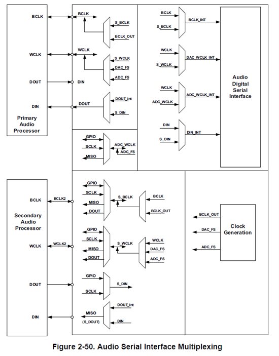
    This is very confusing and even looking at <Figure 2-50. Audio Serial Interface Multiplexing> in document SLAA557, it's not helping.

    Thanks again,

    Benoit

  • All right, I think I've narrowed-it down to the following registers that need to be configured and these are the facts:

    The CODEC input clock will be 2.048MHz coming from my second device. This frequency is too low for the PLL so I'll just route it to CODEC_CLKIN as follows:

    P0_R4: 0b00000010 => GPIO pin is CODEC_CLKIN (GPIO = BCLK2 PIN 32)
    P0_R5: 0b00010001 => PLL is powered down

    P0_R31: 0b00001000 => SECONDARY BCLK = GPIO, SECONDARY WCLK = SCLK

    P0_R52: 0b00000100 => GPIO input is CLOCK input (BCLK)
    P0_R56: 0b00000010 => SCLK input is SECONDARY WCLK

    P0_R11: 0b10000001  => NDAC on, value = 1
    P0_R12: 0b10000001  => MDAC on, value = 1
    P0_R13: 0b00000001  => DOSR on, MSB
    P0_R14: 0b00000000  => DOSR on, LSB, value = MSB | LSB = 256
    P0_R18; 0b10000001  => NADC on, value = 1
    P0_R19: 0b10000001  => MADC on, value = 1
    P0_R20: 0b00000000  => AOSR on, value = 256

    P0_R55: 0b00010000 => MISO output is SECONDARY DOUT

    This is not working but that's what makes the most sense. Pin 11 (DOUT) has nothing.

  • Hi,

    Also, make sure MDAC*DOSR >= RC*32. Same for MADC side. See this app note for details: http://www.ti.com/lit/pdf/slaa404

    Also see this wiki:

    http://e2e.ti.com/support/data_converters/audio_converters/w/design_notes/2740.where-can-i-find-example-scripts-for-these-codecs.aspx

    Regards,

    J-

  • Hi J,

    Thanks for your reply but that's not exactly what I was asking for. I've already looked at these links and I have all the AIC3204 documentation on my PC, everything is opened, but I think I'm missing something in my configuration because there's no audio coming-out of my secondary DOUT pin. Note that my setup works fine when using the PRIMARY I2S port.... but I need this on the SECONDARY I2S port, NOT the primary.

    In your equation <MDAC*DOSR >= RC*32>, what is RC? Sorry for my ignorance, I just can't figure what RC stands for.

    To re-iterate, the BCLK from my external device is 2.048MHz. This will go into SEC_BCLK. The external device also outputs an 8kHz short-sync (DSP mode) clock which needs to go into SEC_WCLK. In return, the CODEC will return 16-bit data.

    So, what are ALL the registers needed to be configured to achieve this AND what values do I need to write to these said registers in order to accomplish this task? Note that the CODEC is configured over I2C therefore it will not be an issue for me if I require to use one of the SPI pins for the secondary port.

    My configuration is in my last post (seen above) but it's wrong because as I said, it works on the primary port but not the secondary.

    I hope this is clearer.

    Thanks again and writing the registers and values in this thread will help other customers because there seems to be other messages with this without an exact solution.

    Benoit

  • Hello Benoit,

    To use the secondary audio interface you need to:

    1. Configure the pin(s) for this function (P0_R52-R56).
    2. Configure the internal interface block to use the secondary interface (P0_R32).
    3. Configure interface signal muxing (P0_R31 and P0_R33).

    Drawing in the diagram below is very useful to determine what is possible and what is not.

    From your settings, it seems that P0_R33_D0 is not being configured. You would need to set it to DOUT_int.

    Regarding you question about RC, it means resource class. Search RC in the app note I mentioned and you will see what I mean. Also, the AOSR value is incorrect and will give a gain error. Refer to the Clock Divider Selection Process table in the app note.

    Also, a 2.048MHz PLL input is ok if you need a sample rate that is a multiple of 8kHz since D=0000. In fact, in such case the master clock frequency into the PLL can go from 512kHz to 20MHz.

    You can use J=48, P=1, R=1, D=0000. For the rest of the dividers, use the values in the second image of this wiki page: http://e2e.ti.com/support/data_converters/audio_converters/w/design_notes/366.help-i-get-a-lot-of-noise-when-my-dac-is-running-at-low-sample-rates.aspx. You will also see in this wiki that a DOSR of 768 provides the best performance for 8ksps.

    Regards,

    J-


  • Thanks for the info. Helped a bit but still had some fiddling around to do since the details were not as explicit as I requested / expected. I don't know this thing off the top of my head like you guys hence the request for exact register and values.

    Anyhow, Important thing is that it now works.

    So, this is how it goes for people interested in using the SECONDARY I2S PORT. Note that the values below are for MY clocks so YOUR values might change.

    Hardware setup:

    I have an MCU (PIC24) tied to the CODEC over I2C. This is important because using SPI, the secondary I2S becomes unusable. The MCU will be configuring the CODEC registers. I also have a communications device tied to the CODEC's secondary I2S port.

    By default, the CODEC has an MCLK of 36.864MHz tied to CODEC_CLKIN but my code will override this clock using the SEC_BCLK pin (CODEC clocks will be provided by my External Communications Device a.k.a ECD).

    ECD will be generating the SEC_BCLK and SEC_WCLK. In return, the CODEC will provide the output audio on SEC_DOUT.

    The SEC BCLK will be 2.048MHz @ 50% duty. The SEC_WCLK will be 8kHz SHORT PULSE (DSP mode, figure 5-50 of document SLOS602A, section 5.17.1.4, page 88). In my case, it is a 500ns high pulse, 124.5us low pulse for a total of 0.125us - 8kHz).

    CODEC pins are used as follow:

    SEC BCLK = Pin 32 GPIO / MFP5

    SEC WCLK = Pin 8 SCLK / MFP3

    SEC DOUT = Pin 11 MISO / MFP4

    Software setup:

    I created myself a function called <SetRegister( page, register, value )> to set individual registers. This function internally communicates over I2C with the CODEC.

    // In this case, I am powering down the PLL. Haven't tried yet with PLL turned-on, not sure how audio quality will change.
    SetRegister( 0, 5, 0b00010001 );

    // GPIO/MFP5 input is routed to CODEC_CLKIN therefore CODEC's MCLK is overridden.
    SetRegister( 0, 4, 0b00000010 );

    // Pin 32: GPIO/MFP5 input will be for Secondary BCLK
    // Pin 8: SLCK/MFP3 input will be for Secondary WCLK
    SetRegister( 0, 31, 0b00001000 );

    // Secondary WCLK = ADC_FS
    // Secondary DOUT from serial interface
    SetRegister( 0, 33, 0b00001001 );

    // Enable secondary interface for audio interface
    SetRegister( 0, 32, 0b00001100 );

    // Pin 32: Secondary BCLK -> GPIO/MFP5 input is a clock input
    SetRegister( 0, 52, 0b00000100 );

    // Pin 11: Secondary DOUT -> MISO/MFP4 is output
    SetRegister( 0, 55, 0b00010000 );

    // Pin 8: Secondary WCLK -> SCLK/MFP3 is input
    SetRegister( 0, 56, 0b00000010 );

    SetRegister( 0, 11, 0b10000001 ); // NDAC on, value = 1
    SetRegister( 0, 12, 0b10000001 ); // MDAC on, value = 1
    SetRegister( 0, 13, 0b00000001 ); // DOSR on, MSB
    SetRegister( 0, 14, 0b00000000 ); // DOSR on, LSB, value = MSB | LSB = 256
    SetRegister( 0, 18, 0b10000001 ); // NADC on, value = 1
    SetRegister( 0, 19, 0b10000001 ); // MADC on, value = 1
    SetRegister( 0, 20, 0b00000000 ); // AOSR on, value = 256

    I also enabled AGC to prevent audio clipping.

    This is my solution and works perfectly.

    Thanks for your help.

  • Hi Benoit,

    I'm glad to hear it worked!

    One thing though, again I would recommend setting AOSR and DOSR to a value optimal for you processing block and sample rate. For Filter A (search Filter A in application reference guide and Design and Configuration Guide app note) you should use an AOSR = 128. A value of 256 will cause clipping.

    So looking at your settings, set NADC = 1, MADC = 2, AOSR = 128. Then NDAC = 1, MDAC = 1 DOSR = 256 is fine, although some out of band noise may affect SNR numbers. Optimal DOSR for 8ksps is 768, but you'd have to use the PLL for your configuration.

    Regards,

    J-