This thread has been locked.

If you have a related question, please click the "Ask a related question" button in the top right corner. The newly created question will be automatically linked to this question.

SRC4382 Ratio Register Read issue

Other Parts Discussed in Thread: SRC4382, SRC4392

I'm using 2 src4382's in a design that for this version is only using the AES DIR and DIT as s/pdif through the src. I'm using an Atmel ATTiny44 as the controller. It is all working as it should as I used the EVAL board to learn how to set up the src4382. The problem I'm having and this is the show stopper is the behavior of the the Ratio Read registers 0x32 and 0x33. I am using a dual frequency programmable 3.3V MEMS oscillator, a Silicon Labs 502BBD-ADAF with freq 1 programmed to 24.5760mhz and freq 2 programmed to 22.5792mhz. I've verified the frequencies are accurate and programming PORT A and or B and probing the L/R clock shows the proper frequency (using a scope with frequency counting).  I am using the MCLK (pin25) input for all clocks. for the 24.5760mhz clock I'm using P=2, J=2, and D=0 (Receiver PLL configuration registers 0x0F, 0x10, 0x11), and for the 22.5792mhz clock I'm using P=2, J=8, D=7075 (decimal). The whole system works well, locks to the incoming stream and properly encodes an s/pdif output. This has been verified at all frequencies with recording studio s/pdif equipped devices. IT works, passes audio and sounds great.

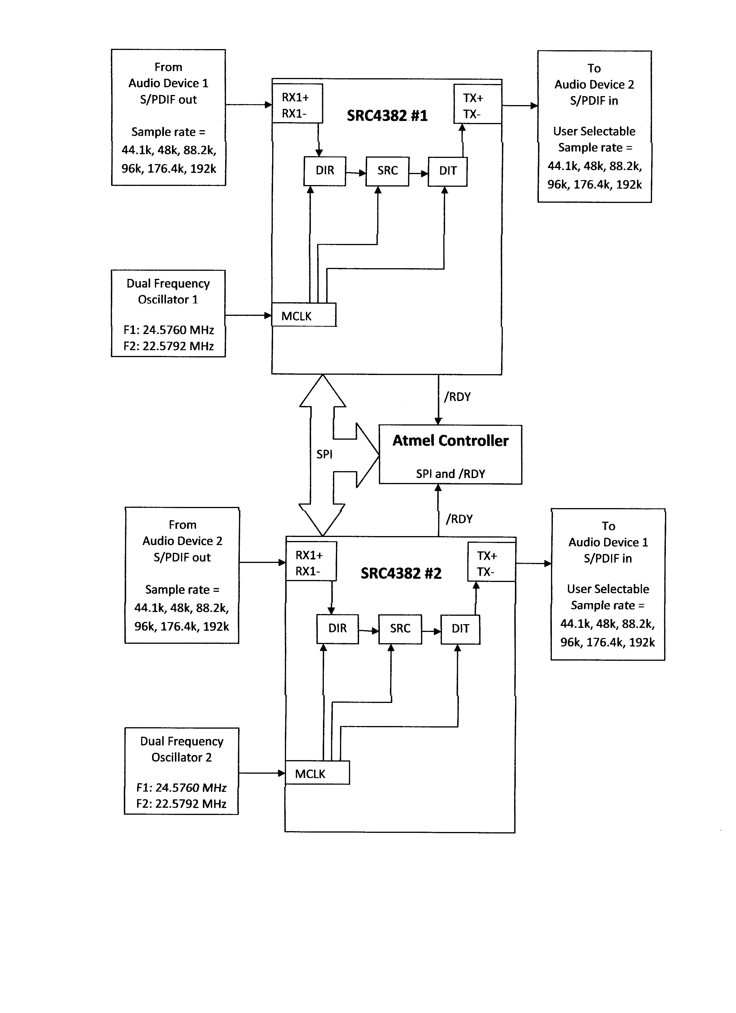
The 'showstopper' for this device with 2 src4382 is due to the requirement that either of the src's need to be made a 'master' or 'slave'. The idea is the an s/pdif output from the sending device enter's src1, is sr converted to a user selectable sr and goes out to a different s/pdif device's input. The output from that device's s/pdif stream then goes into src 2 (at the src framerate of src1) is converted to the src rate at the input of src1 and then sent to the originating device. This scenario is equivalent to an analog patch bay with an outboard device in the efx loop.

To accomplish this I need to know the I/O sample rate ratio. I have the /LOCK pin connected to a 2ma led (for lock indication) and also to a pin on the controller set up as an interrupt so it can interrogate the SR Ratio regs at the proper time. It all works as it is supposed to except the SR Ratio register is exhibiting some anomalies. When I have the MCLK pin receiving 24.5760mhz and the input is receiving 48khz, 96kz, or 192khz frame rates (pure integer ratio's : 1,2, or 4) register 0x32 reads back as all 1's, and register 0x33 reads back as all 0's.  Decoded and bit shifted I get 0x1f (register 0x32) and 0x07 (register 0x33). I get the same behavior if MCLK is receiving 22.5792mhz and the receiver input is getting 44.1khz, 88.2khz, and 176.4khz frame rates (again pure integer ratios). However it all works like it's supposed to when I have the MCLK pin receiving 24.5760mhz and the receiver input is getting 44.1khz, 88.2khz, and 176.4khz frame rates and conversely with MCLK inputting 22.5792mhz and the receiver getting 48khz, 96khz, and 192khz frame rates. I get the ratios reported as they should be.

Obviously, if I can't know what the ratio is I can't know the proper divisor to use to set up the 'slave' src to mirror the 'master' src. I've tried everything I can think of and have looked through all the src4382 and src4392 threads relating to the ratio registers and tried those remedies also. I have not had any joy up to now.

At this point any help or knowledge of what I may be doing wrong or misinterpreting would be most welcome. Failing that, I would have to assume that this may be a bug in the silicon on the version I'm using? The part number stamped on the package is: SRC4382I , next line: 36C0GTT.

  • A couple of errors to correct on the above post.
    1: I'm using the /RDY pin not the /LOCK pin.
    2: Register 0x32 decoded and bit shifted reads back as 0x1f and 0x07 with whole integer ratios. Register 0x33 is always all 0's. I'm assuming the granularity of the sample rate ratios that are getting reported is to large to trigger any bits in that register.
  • Hi Roger,

    I'm having a tough time understanding your application, would it be possible to put together a basic block diagram of the inputs and outputs and clocks needed? Does your output audio range change as well as your input rate? Are the two SRC4382s connected to the same input, passing through each other? or not connected at all?

    Once I can get a better picture of your application i will be able to provide better assistance.

    Justin
  • Hi Justin, thank you for responding. The 2 src4382's are not connected at all except through the spi interface and they are enabled through the /CS pin. They are essentially 2 separate systems, with their own inputs and outputs, each with their own clocks. In one mode I would like to set the output frame rate of src 2 to the input frame rate of src 1. In the other they would work as sepate systems sharing only the spi and the power supply.

    For clocks, to each src4382 I am using a single dual frequency oscillator that provides 24.5760mhz and 22.5792mhz to their MCLK pins. I am using this clock for the DIR, SRC, and DIT blocks.

    In 'Mode 1' The 2 src's are independent and can be set to run any way the user see's fit.

    Audio Device S/PDIF out -->[RX1 in DIR]. DIR --> SRC. SRC --> [DIT out TX] --> Audio Device S/PDIF in.

    MCLK is the clock for all blocks. MCLK is driven from a dual frequency oscillator. F1 is 24.5760MHz, F2 is 22.5792MHz. The user can set the output to one of 6 frame rates. 44.1k, 48k, 88.2k, 96k, 176.4k, 192k. The 48k, 96k, 192k rates are done with the 24.5760MHz clock and dividing the MCLK rate in the DIT by 128, 256, or 512. The other 3 are done with the 22.5792MH clock the same way. The 2 frequencies for each oscillator are selected from the micro-controller using 2 different pins so they are independent. When used this way knowing the SRC in/out ratio is unimportant.

    In 'Mode 2' The src's can be set so that the output frame rate and MCLK oscillator of src 2 can be set to the incoming frame rate and MCLK oscillator of src 1, or vice versa, user selectable. A typical setup would be Audio Device 1 would be a digital mixing desk or DAW interface with S/PDIF I/O ports connecting to Audio Device 2, a digital reverb with S/PDIF I/O ports. Audio device 2 would be set to say 48k frame rate (due to interface frame rate constraints) and Audio Device 1 would be set to 96k. The user would set SRC1's output to 48k. With 96k coming in it would Lock then the PLL's would resolve and /RDY would go low. According to the data sheet the SRC I/O Ratio Registers 0x32 and 0x33 can be read any time the /RDY signal is low. In my case at this time when /RDY goes low I need to read the Ratio registers and apply the inverse of the Ratio to src 2 and set the output divider accordingly to automagically set the output frame rate of src2 to the input frame rate of src 1. That is the extent of one device 'slaving' to the other. Conversely the user can select src 2 to receive the input from Audio Device etc, and set src 1's output frame rate to src 2's input frame rate.

    This way the sample rates can be switched transparently.

    The problem I'm having is this doesn't work in my configuration. When the incoming frame rate is whole integer to the output frame rate register 0x32 reads all one's and register 0x33 reads all zero's. i.e. If I have 48k coming in to SRC #1 with MCLK receiving 24.5760MHz, the Ratio registers read 0xff and 0x00 when /RDY goes low no matter what the transmit divider is set to. If I have 44.1k coming in to SRC #1 with MCLK receiving 22.5792MHz I get the same result. However, if I have 48k coming in to SCR #1 with MCLK receiving 22.5792MHz the Ratio registers will read correctly. If I have 44.1k coming in to SRC #1 with MCLK receiving 24.5760MHz the Ratio registers will again read correctly.

    Thanks again for you attention to this matter.

  • After many more tries of using different configurations including using a dedicated oscillator for the RCKI and routing that to just the DIR and using MCLK for the SRC and DIT, and other combinations of clock routing, ex. DIR->PORTA->SRC->DIT, DIR->SRC->PORTA->DIT, etc. (these were made to work correctly as far as doing SRC from DIR through the various routes to the DIT). I also got the system to work using the Interrupts and found that not reading certain registers after an unmasked interrupt bit keeps the /INT line asserted. I have exhausted all the variables that I could come up with, both read from and implied from the datasheet. This problem is present in all 4 src4382's I bought off the shelf that have the same lot code.

    I took my EVM with an src4382 off the shelf and it had a different lot code on it, hooked it up and wrote a script to mimic the setup on my proto board. I even used one of the src's on the proto board to provide an s/pdif stream and the different clock rates I will need. The eval board locks and shows rdy  on all the different frame rates applied. When I read register 0x32 and 0x33 on the eval board they report correctly at all frame rates. I'm also using the 24.5760mhz oscillator on board and running that to MCLK and using the SPI interface. The only logical conclusion I can come to is the lot number of the src4382's I have are exhibiting this behavior due to a bug. I don't know where I could find a part with a different lot code or whether it would matter. There was a thread that someone used an src4382 and similar results as me, but it DID work...sort of. The price difference of using an src4392 in it's place is prohibitive in this application, so unless someone can provide a 'work-around' or someone from TI can either confirm or deny this, I'll have to reject the part and the design, or design my own frequency counter on board...again too pricey for the solution.

    Has anybody run into this problem? It would be great to know. If not, what were your lot codes? If yes, were you able to work around the problem?

  • Hi Roger,

    Would it be possible for you to send me your register settings? There's quite a few settings in this part and I would also like to replicate your setup on the EVM.

    Justin
  • Hi Justin, I had put the project away for a bit and got back to it yesterday. I re-examined my code and found that I had a bug in my register read functions. i.e. I was skipping the first register and reading the second. I was using a dummy byte before the read also. My bad. After I fixed the read portion, I can now read the registers correctly. However, on my board as the block diagram indicates I have 2 src4382's. One of them displays the correct ratio values:

    output rate = 48k

    input = 48k: register 0x32 = 0x08, register 0x33 = 0x00

    input = 96k: register 0x32 = 0x10, register 0x33 = 0x00

    input= 192k: register 0x32 = 0x20, register 0x33 = 0x00

    the same values are shown for an output rate = 44.1k and inputs of 44.1k, 88.2k, and 176.4k

    the other one displays these values:

    output rate = 48k

    input = 48k: register 0x32 = 0x07, register 0x33 = 0xff

    input = 96k: register 0x32 = 0x03, register 0x33 = 0xff

    input = 192k: register 0x32 = 0x01, register 0x33 = 0xff

    This has me scratching my head as the code and settings are identical for both parts. I thought I had ruined the part with bad readings, so I took it off and installed a new one, but got the same results. This got me wondering if my oscillator has too much jitter. The specs I have are for 100mhz operation.

    cycle to cycle: 16ps, 26ps maximum

    period jitter: 1.3ps, 1.9ps maximum

    period jitter (pk to pk): 10k samples, 10ps typ., 16ps max

    phase jitter: 75 MHz, F offset=900 kHz to 7.5 MHz: 2.5ps rms typ. 3.5ps rms max

    The jitter for the oscillators (Pletronics SM7745HSV-24.576M and 22.5792M) on the EVM are:

    Jitter - 0.6 pS RMS 12 KHz to 20 MHz from the output frequency - 2.5 pS RMS 10 Hz to 1 MHz from the output frequency

    There is no spec for minimum allowable jitter for the src4382, but the spec for the recovered clock output jitter is 200ps on the data sheet. Is it possible there is too much jitter for the rate estimator with the oscillators I am using?

    I would be happy to send you my C code or I can send you pseudo-code of the setup for the registers. I would just need a place to send it to.

    Again, thank you so much for your help.

  • Hi Roger,

    I am glad progress is being made, as for the second part were you able to capture the communication between the MCU and the part to verify the communication was correct? If you could send me the pseudo-code for the register setting I could replicate your settings myself next week.

    I don't think the level of jitter produced by the oscillators are a problem, they seem well within reasonable limits. Do you have two parts total, or have you tested more than two parts/boards?

    Justin