This thread has been locked.

If you have a related question, please click the "Ask a related question" button in the top right corner. The newly created question will be automatically linked to this question.

Test Patterns in ADS4229

Other Parts Discussed in Thread: ADS4229

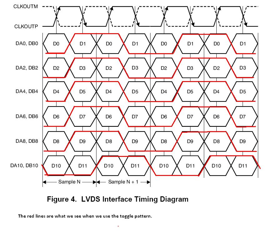
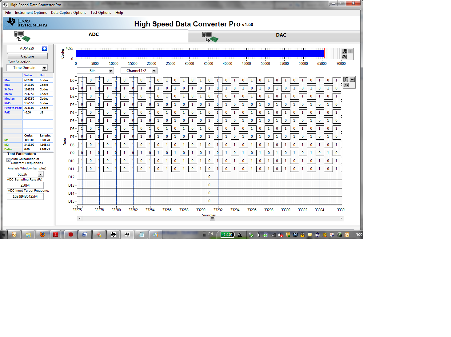
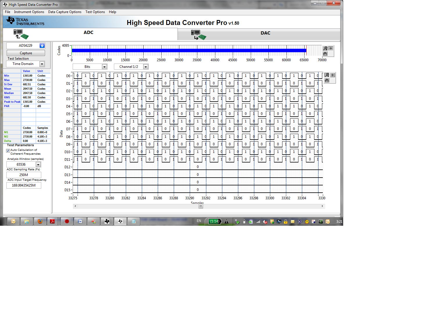
After configuring the test pattern (either custom pattern or toggle pattern), the most significant pair of both channels (DA10P & DA10M and DB10P & DB10M) doesn’t behave like the rest of the pairs, which prevents us from synchronizing.

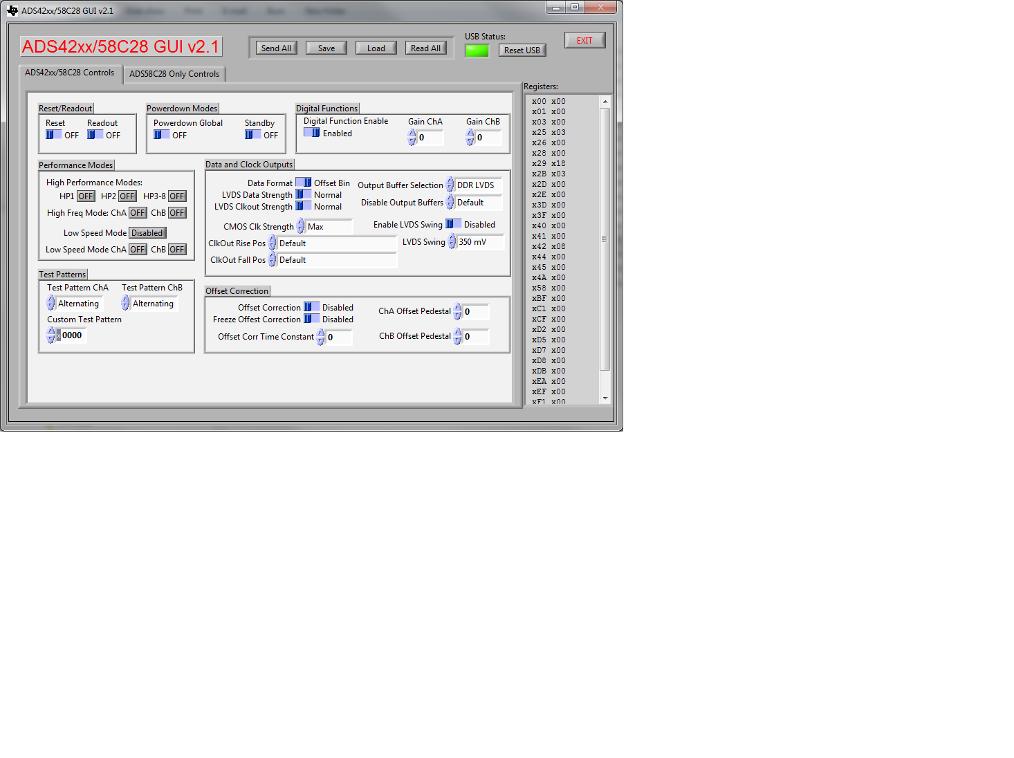
The configuration registers were written as follows:

Addr                      Data

REG0                    8'h0

REG25                  8'h05

REG29                  8'h18

REG2B                  8'h05

REG3D                  8'h0

REG3F                  8'h2a

REG40                  8'ha8

REG42                  8'h08

REG4A                  8'h00

REG58                  8'h00

REG2                    8'h00

REGD5                  8'h00

REGD7                  8'h00

REGD8                  8'h00

I'd be happy to provide more information as requested.

  • Hi,

    We've never had MSB problem before with this device on EVM but I'll check this configuration on EVM tomorrow and get back to you. If we had MSB issue, we wouldn't get the correct output spectrum from pattern capture card. Anyhow, I'll update you with this soon.

    Thanks,

    KW

  • Hi KW,

    Thanks for your reply!

    It would be great if you could try that out. I don't have an EVM, but if I load that configuration from a .txt file into the GUI, it doesn't display the right options on the left.

    Thanks,
    Andres

  • Hi Andres, KW,

    While visitng Andres' lab on Friday, he showed me a diagram that explains the error. It looks like DA10 and DB10 are delayed in the time-domain, but they noticed that D11 is basically following D10, shown below:

    What could cause this to happen? The register values they are loading (shown above) look reasonable. Is there a particular order the registers have to be loaded that can cause error?


    Thanks,

    Bryan, Sunnyvale Field Apps

  • Hi, Bryan

    ADS4229 device looks working well with toggle (Alternating) pattern. From register setting, you'll be using offset binary for data format. With this, you'll have this problem because bit 11 is swapped from the bit processing of offset binary (Internal pattern is based on two's complement) . With this MSB (bit 11) inversion, it looks delayed bit shown as above but it is not.

    But it should be ok with two's complement of register setting, which bit 11 toggles at every clock. This is not an issue but the different bit processing between offset binary and two's complement out of device.

    Please refer to attached screen shots.

    < Captured GUI with register settings >

    < Toggling from offset binary setting from GUI >

    < Toggling from two's complement setting from GUI >

    Thanks,

    KW

  • Hi KW,

    Thanks for your reply.

    It's interesting to know that this behavior is the expected one.

    I was wondering if there's any place in the datasheet where it mentions that the MSB toggles differently when using offset binary, or that the ADC does not output the loaded test pattern.

    Thanks,
    Andres