This thread has been locked.

If you have a related question, please click the "Ask a related question" button in the top right corner. The newly created question will be automatically linked to this question.

TSW54J60/ADS54J60 interleaving correction behaviour at fs/4

Other Parts Discussed in Thread: ADS54J60, LMH6401, LMH3401

Hi!

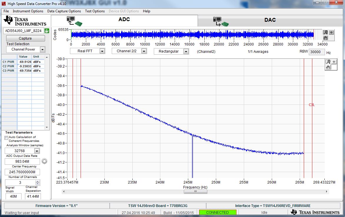
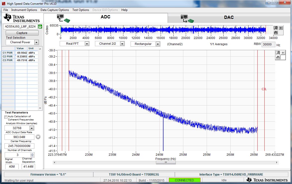
I’m using the TSW54J60 (Rev B) for the feedback of a large bandwidth DPD system(Tx=TSW38J84,FPGA=VC707). I’m using discrete multitone signals with up to 200MHz bandwidth. I’m locating the IF at fs/4 (fs=8x122.88=983.04MHz) to get the maximum bandwidth out of the device (bandwidth of approx. 4x122.88= 491.52MHz).

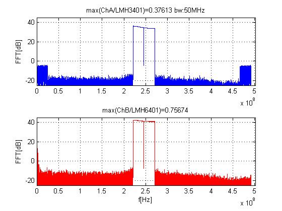
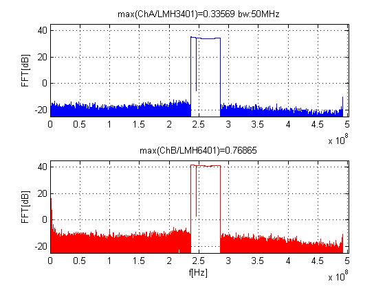
The problem is now that the interleaving correction does not work stable for signals located at IF=fs/4. The inband noise jumps (randomly) and is not constantly low as I would expect. I also tried to shift the signal slightly away from fs/4 which results in much better performance. But I still see sometimes the IL spurs...

For example: For a 50MHz bandwidth DMT signal I have seen better than 50dBc SNR. When the IL correction fails the SNR drops below 40dBc.

Another problem is that I don’t get any tone at fs/4. It’s almost cancel out by the ADC. Is this a normal behavior of this ADC? I cannot explain how it is possible that the fs/4 tone can be canceled out???

I have done a lot of test also with your provided config files but without success…

Using analog/digital reset does not lead to better results.

Have you ever seen such behavior on the ADS54J60 / TSW54J60??

Have you ever tried the TSW54J60 on the VC707 (FMC2 J37)??

How can I get the ADC interleaving correction stable?

Why (or better how) does the ADC kill the tone on fs/4 (2x122.88MHz)?

The JESD is working fine and I use the 4-Lane 8224 Mode with Scrambling enabled. I almost use 1dB fullscale of the ADC.

I appreciate any answere/help!!

Best regards!

Martin

Some off topic question/hint: The "Scrambling EN" checkbox of the ADS54JXX GUI (v1.5) does not work. Since it happens nothing (the GUi doesn't send something) when I press it, I think its just the checkbox without any connection in the background... I had the same problem with the previous GUI version. Maybe its again a problem of my PC,... but its just a checkbox and all others do work,...

  • Martin

    We are looking into this.

    Regards,

    Jim

  • Martin,

    Are you using bypass mode for all of these tests? Have you tried capturing the data with the TSW14J56EVM? How many multitones are you testing? Which channel are you using, LMH6401 or LMH3401? Has the board been modified for DC-coupling? This information will allows us to duplicate your test setup. 

    Regards,

    Jim

  • I use the Xilinx VC707. I have never tried the TSW14J56EVM. I'm using a DMT signal with 2^15=32768 Samples. The maximum #of tones of this signal lenght with for example 50MHz bandwidth is 1666 (tone spacing=~30KHz). I use both channels at the time with the same signal. Later on it will be two different signals. I have not done any modifications to the EVM. (so I’m still using AC coupling)

    Since everything is locked together I can use coherent sampling and feeding back the exact same length signal. I just capturing and reading the feedback signal continuously and displaying it with Matlab (about half a second per iteration). I can also

    We have also a lot of IP running inside the FPGA and MATLAB but for these tests everything is off and I just look to the feedback without updating the TX signal. Later on I also update in every iteration the TX signal but then the ADC behaves then even more worse…

    Here are some snapshots:

    Idealy the FB looks like:

    The spectrum schould be flat and clean. You see that there is allmost no FS/4 tone. I have verified that the tone is existing on the input signal of the ADC EVM (demodulator output).

    I have somtimes these images on the FB:

    I see them in some iterations on the A channel and somtimes on the B channel.


    Here i go slightly away from the fs/4. There you see that the fs/4 tone still have been canceled out...

    Then i can go up to a higher IF where the performance is better but i still  get sometimes images in the spectrum.

    To keep the setup simple vor this tests i have no amplifier inside which limits at the time the FB power to the maximum available by the TSW38J84.

    So you see that the input is a little bit below the recommendet 0.5dBFS. I see a littel  improvement in the behaviour of the ADC when i increase the input power but its still not free of IL images. I have also the 6dB attenuators on the ADC inputs.

    best regards

    Martin

  • Martin,

    What is the end application for your design? Can you tell us who the customer is? 

    Regards,

    Jim 

  • The end application is a broadband DPD system for next generation base-station PAs. Our customers are leading base-station vendors.

    Martin

  • Martin,

    Can we get the schematic of his board? What all SPI registers are they programming?

    Regards,

    Jim

  • Martin,

    We generally expect the spurs to be removed consistently and do not expect any sporadic occurrence of spurs. Anyway we are trying to recreate this scenario in the lab. What is the average power of the 50 MHz BW signal input to the ADC? The peak power seems to be -0.5 dBFS. Please confirm this.

    Signal notch at fs/4 is expected. We remove DC from the ADCs and as part of this, the signal at fs/4 is also notched out. Let us know if it is a problem.

    Regards,

    Jim

  • The DMT test signals we are using have a crest factor of approx. 7 to 8dB. Peak Power power is in the range of -3 to -0.5dBFS deppending on the test signal and DPD behaviour.

    Martin
  • Martin,

    Here is some more info from the design team:

    We do not see any unexpected behavior with DMT signal. See attached test report.

    Can customer provide us with exact sequence of SPI writes they are using? It seems IL engine is not working for them due to some reason when they see big spurs.

    A clarification (if customer asks), that integrated IF power reported in PPT is ‘peak power’ not average power of DMT signal.

    Since if peak power exceeds 0dBFS, ADC will saturate; you see it saturating in last slide.

    Regards,

    Jim

    ADS54J60_with_DMTsignal.pptx

  • Here are the config files. They are based on your reference configs which you have provided with the TSW54J60 GUI. For the test-setup i’m using the TSW54J60 on the VC707 (FMC2 J37).

    I’m using a 122.88MHz reference clk on LMK CLKin (J6). Then the LMK is supplying all necessary clks. Also the 122.88MHz glblclk and the 491.52MHz refclk for the Xilinx JESD204b IP (CLK_LAO_0P/M  and FPGA_JESD_CLKP/M). The ADS54J60 JESD is running in 8224 mode + Scrambling.

    I will also try to get the TSW14J56EVM to do tests with that one too.

    Best regards!

    Martin

    0020.x5_TSW54J60_2_adc.cfg

    3733.x5_TSW54J60_1_lmk .cfg

  • 0020.x5_TSW54J60_2_adc_new.cfgMartin,

    There were several extra reset write commands and a few invalid register writes in the file you sent. Please try using the new one attached.

    Regards,

    Jim

  • No success,…

    Some time ago, I have tried your reference config files from the GUI but I always had the same problem with the interleaving correction. So I don’t think that the problem is related to the config files. I also don’t think that there is something wrong with the ADC or the eval board,…

    I also bypassed the LMK VCO (LMk in clk distribution mode) and have used my own clk without success,..

    Is it possible that the JESD interface (Xilinx FMC interface or the IP) influences the IL correction in some way? What else could have influence on your IL correction?

    I have also tested your TSW38J84 on the VC707 witch works great under every condition,…

    Best regards!

    Martin

  • Martin,

    I would like to attempt to duplicate your test as close as possible. I have a multi-tone generator I can use for a source. I will center the tones at 245.76MHz. How many tones did you use, and at what amplitude? I can try this first with our TSW14J56 capture card, then on a VC707 platform.

    Regards,

    Jim

  • Martin,

    What is marked on the ADC device? We want to make sure your are not evaluating a pre-RTM device by accident. What is the exact analog input frequency range?…basically we need to know which Nyquist you are operating at and verify that your are apply the appropriate Nyquist register setting.

    To enable Nyquist control, write the following:

    0x68004E 0x80 Enable Nyquist control

    Program Nyquist zone setting accordingly:

    0x680042 0x00 for 1st Nyq

    0x680042 0x01 for 2nd Nyq

    Apply Pulse RESET for these bit to become effective:

    0x680000 0x01  PULSE RESET bit set high

    0x680000 0x00  PULSE RESET bit set low so that it is ‘pulsed’.


    What is exact sysref frequency?


    We tested a device near fs/4 (260MHz IF, 15MHz BW for DMT signal) and did not see any unexpected behavior.

    Regards,

    Jim

  • On the device is marked:

    AZ54J60

    TI 574

    ZOHE G4

    (TSW54J60 EVM Rev B)

    We want to use as much input bandwidth as possible (0-fs/2). The maximum bandwidth will be 200MHz+PA nonlinearities. This will be centered at fs/4. At the time, I use 50MHz bandwidth signals to test the ADC behaviour. The final application bandwidth is dependent on the standard which will be covered by the PA. Put we want to be as flexible as possible,… We are using the first Nyquist zone. ADC is configured properly. We are using exact FS/4 as the input frequency.

    Sysref Frequency is fVCO =2949.12/768 = 3.84MHz

    Best regards

    Martin

  • Martin,

    Which path are you using on the EVM? What is the gain setting if you are using the LMH6401 path? You mentioned a 50MHz BW input signal? Was this multi-tone? If so, how many? What is the amplitude of these tones at the input of the ADC?

    Regards,

    Jim

  • I use both pathes. Yes, most of the time I’m using broadband DMT signals with 50Mhz, ~8dB PAPR, 32k Samples long and a ~1.6k tones. But I also have done tests with other signals. Actually, I don’t see any relationship between the input signal and the IL behavior. I have problems with every input signal. So I think the problem is not the input signal. Gain setting of the LMH6401 is 0x3. Input is around -3...-0.5dBFS.

    Best Regards
    Martin
  • Hi!

    I have made some tests with your TSW14J56. I still see sporadic spurs in the spectrum of the ADC due to the ILC behavior.

    But the bigger problem for me is that the inband distortion also increases sometimes.

    Here an example for good performance:

    And here one for bad:

    Is this an expected behavior of the ADC ILC when I’m using a DMT located at fs/4 ??

    Sometimes the ILC is also stable and performs very well. But sometimes also not,…

    best regards!

    Martin

  • Martin,

    Can you reproduce the problem with single tone input? We are unable to observe what you are seeing in our lab, even with a DMT signal. If you want, please ship us your board to test here and/or we could ship you a new board.


    Regards,


    Jim