This thread has been locked.

If you have a related question, please click the "Ask a related question" button in the top right corner. The newly created question will be automatically linked to this question.

ADC12DJ3200EVM: ADC12DJ3200

Part Number: ADC12DJ3200EVM
Other Parts Discussed in Thread: ADC12DJ3200, TSW14J57EVM,

Hi TI team,

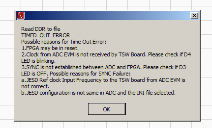
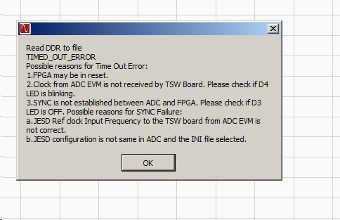
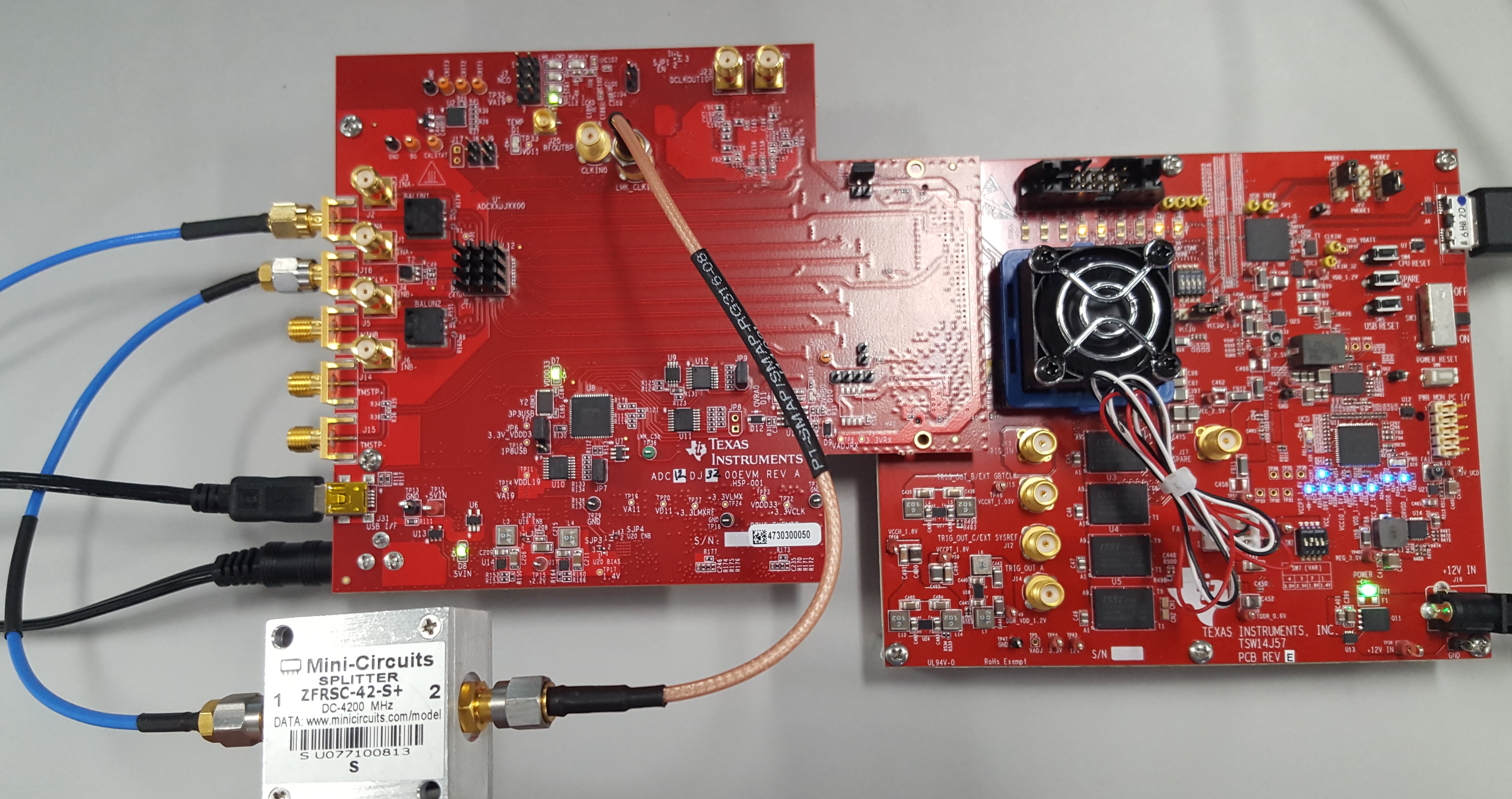
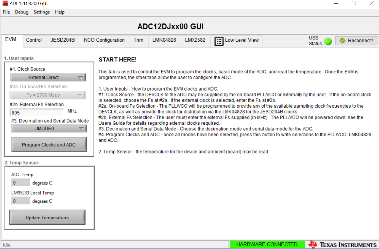
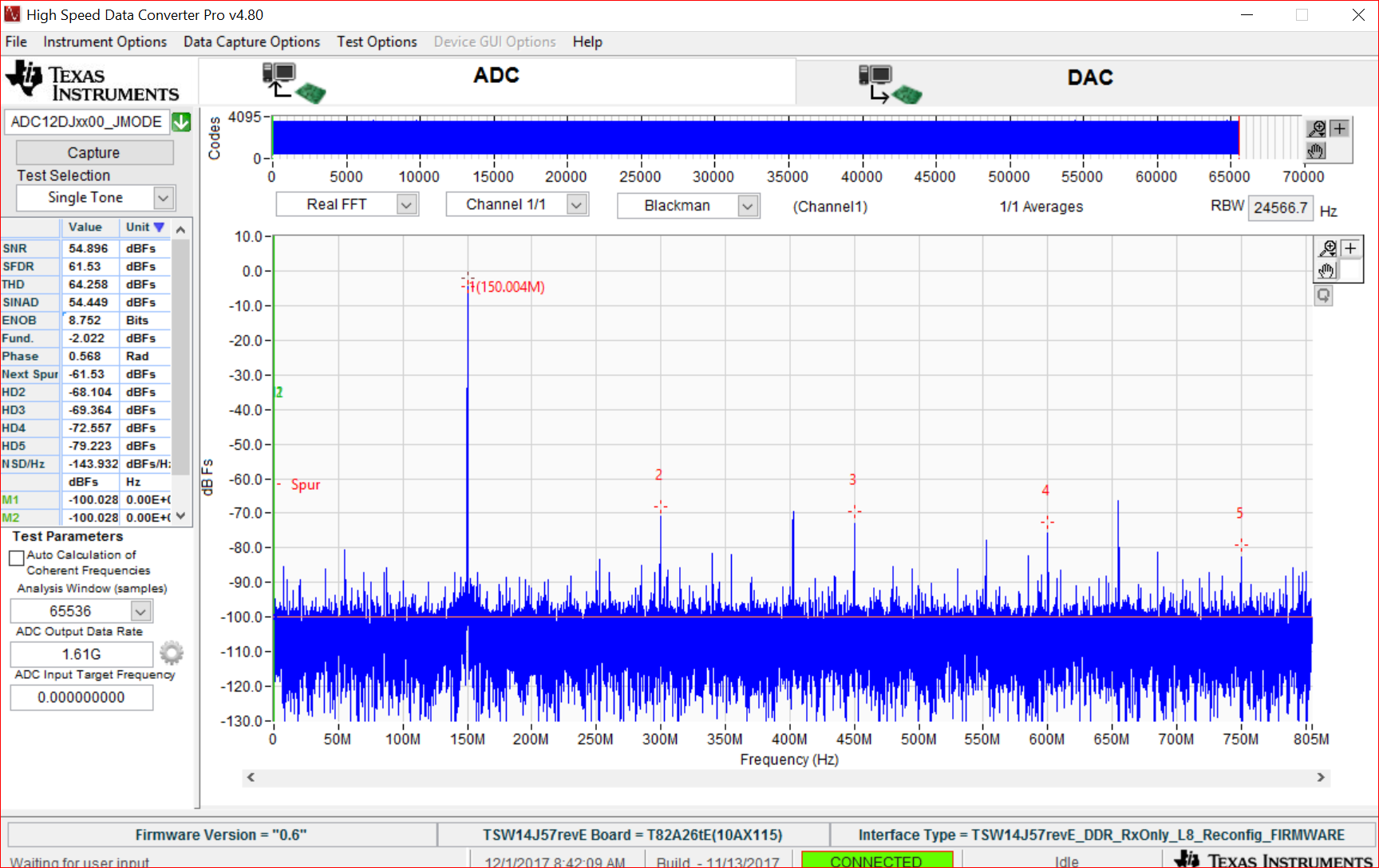
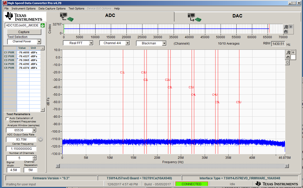
When I am evaluating ADC12DJ3200 EVM. I configured for 2700 Msps with JMODE16 it working fine. But when I configured to "800" MSPs with JMODE 16 and similarly configured for JMODE0. In both cases it throwing error. I verified as per error thrown on hardware D4 is not blinking and D3 glowing up. I am thinking like clock is not going From ADC board to TSW FPGA board.but as per data sheet it should support 800 Msps also. may I know the what could be the reason for this problem.? Is this due to hardware limitation or we are missing any config settings.

  • Hi aamancha Raghavendra chary,

    I am taking a look into this issue, and will get back with you soon.

    Regards,

    Dan

  • Hi aamancha Raghavendra chary
    Are you using the TSW14J57EVM for data capture, or the TSW14J56EVM?
    Can you try keeping the ADC settings the same (JMODE16, 800MSPS) but change the ADC sample rate entered in High Speed Data Converter Pro to be 1000MSPS instead of 800MSPS?
    Best regards,
    Jim B
  • Hi TI team,

        Here we are using  TSW14J57EVM.As you said we kept the ADC settings the same (JMODE16, 800MSPS) and changed the ADC sample  in High Speed Data Converter Pro to be 1000MSPS instead of 800MSPS.Still it throwing error. and D4 LED is no glowing and D3 is Glowing.

    Best regards,

    Raghavendra chary

  • Hi TI team,

         Could you please look in to above mentioned issue. It is bit urgent task for me.

       Thanks,

      Raghavendra.

  • Hi Raghavendra,

    We are still investigating the issue with using the 800 MHz clock source. In the mean time, I have outlined a procedure below to sample with a clock source as low as 805 MHz.

    First, the ADC12DJ3200EVM hardware must be modified to receive an external clock. Please follow the instructions from the user guide (below).

    In my setup, I have used a single signal generator with a power splitter to provide both clocks (J18 and J22). If taking this approach, make sure your signal source amplitude is high enough to compensate for losses due to splitter. Set the signal source to 805 MHz.

    In the ADC12DJ3200 GUI, select "External Direct" as the clock source, and enter "805" in the "External Fs Selection" field. I am using JMODE0 here. Click "Program Clocks and ADC".

    In HSDC Pro, select "ADC12DJxx00_JMODE0", and enter "1.61G" in the "ADC Output Data Rate" field. After clicking capture, you should see an fft that includes your input signal (150MHz here).

    Please let me know if you have any issues getting this to work properly.

    Regards,

    Dan

  • Hi Raghavendra

    Can you try using JMODE15 instead of JMODE16? I think the issue is related to the FPGA firmware not handling the low serial data rate utilized in JMODE16.

    JMODE15 uses 1 instead of 2 JESD204B data lanes, so the serial data rate is 2x that of JMODE16. It provides the same ADC functionality and I have validated this mode with the TSW14J57EVM capture board. I have noticed one bug, that the data capture sometimes swaps the data from A and B channels of the ADC. If you don't see the expected tone on Ch1 change the selected channel to Ch3.

    Here is an example with Fs = 800 MHz, F_NCO = 82.77MHz and F_IN = 2482.77MHz.

    Best regards,

    Jim B

  • Hi TI team,
    When I measured "Noise floor" at different Sampling rates (800,1500,3000MSPS) with JMODE15, I observed  6 dBc Delta from higher sampling rate to lower sampling rate. also I am attaching some pics. Is this noise floor degradation expected? if so why ?

    Noise Floor
    JMODE15 JMODE16
    Fs(MSPS) NCO=3/4*Fs dBFs/Hz dBFs/4.5MHz dBFs/Hz dBFs/4.5MHz
    800MSPS 600Msps -142.68 -76.15 - -
    1500MSPS 1125Msps -144.83 -78.30 -146.63 -80.10
    3000MSPS 2250Msps -148.03 -81.50 -147.03 -80.50

  • Hi TI team,
    When I measured "Noise floor" at different Sampling rates (800,1500,3000MSPS) with JMODE15, I observed  6 dBc Delta from higher sampling rate to lower sampling rate. also I am attaching some pics. Is this noise floor degradation expected? if so why ?

  • Hi Raghavendra

    The ADC has a fixed amount of noise power at the input spread over the input bandwidth of the device. Whatever the sample rate is, this noise all folds into the Nyquist zone presented in the FFT.

    As the sample rate is increased, this fixed noise power is spread out evenly across the larger Nyquist zone, so the dBc/Hz value drops proportionally. This means that the amount of noise in a fixed bandwidth (4.5 MHz) also drops proportionally as sample rate goes up.

    I'm not sure why the earlier JMODE16 results don't agree with the expected JMODE15 data. It would be good to re-do that test to double check.

    I hope this is helpful.

    Best regards,

    Jim B

  • Hi Ti Team,
    As you suggested I did recheck, Still same values repeating what I mentioned above in jMODE16. can you guess what could be the reason?

    and also when we moved to EXT clock mode in both JMODE16 and JMODE15 (Fs=3000MSPS,NCO=2250Mhz,Fin=2300Mhz)if I enable Average FFT 10 times, it is capturing only some captures not all(10 times). May I know what could be the reason for this?
  • Hi Raghavendra

    If captures are intermittent with external Fclk = 3000 MHz try a slightly higher or lower clock amplitude to see if that changes the behavior.

    For best performance you should be using a bandpass or lowpass filter to remove harmonics and noise from the clock. Ensure that the filter used is properly aligned with the clock frequency.

    Best regards,

    Jim B

  • Hi Raghavendra
    Have you made any progress with the intermittent capture issue?
    When I have encountered this in the past with external clocking the issue was caused by poor synchronization between the 2 external clock generators. To verify this connect the output of both generators to a high speed oscilloscope and confirm the phase relationship is constant. If the clocks are not frequency and phase locked the captures will not be consistently good.
    Best regards,
    Jim B