This thread has been locked.

If you have a related question, please click the "Ask a related question" button in the top right corner. The newly created question will be automatically linked to this question.

DAC38RF82EVM: Problem using Dual DACs with 12 bit resolution

Part Number: DAC38RF82EVM
Other Parts Discussed in Thread: LMX2581, LMK04828BEVM, LMX2592, LMX2582

Hi Jim Seton,

I have been having some problems getting the DAC38RF82EVM to communicate with the TSW14J56EVM (no blinking LEDs, no successful transfer of external pattern file) when I use one particular HSDCPRO .ini file:

DAC38RF8x_LMF_823  <== Dual DACs (12 bit resolution), Real values, 4 Lanes, 2x Interpolation.   

I am using an External DAC clock running at 6.4 GHz (~ 16 dBm tone w/o spurs, input into SMA "DACCLKP").    Using the exact same clock setup, I *am* able to use a related HSDCPRO .ini file:

DAC38RF8x_LMF_821  <== Dual DACs (14 bit resolution), Real values, 4 Lanes, 4x Interpolation.   

With this .ini file, I am able to communicate with the TSW14J56 (blinking Tx CLK LED, no memory error), load a single tone, load an external pattern file, and measure the expected RF output on the Channel A and Channel B  ports (SMAs J6/ IOUTA and J2/ IOUTB_SE.

Any idea why one configuration works fine and the other doesn't?

Ultimately I would like to run the DAC with the following set-up:

DAC38RF8x_LMF_823  <== Dual DACs (12 bit resolution), Real values, 4 Lanes, 1x Interpolation.  Direct External Clock at 3.2 GHz

but I need to get an RF synthesizer (I'm thinking LMX2581) that will output a clean (no-spurs) tone @ 3.2 GHz.

Any advice you could give about working with the 12-bit Dual DAC configuration would be greatly appreciated.

Much Thanks,

Steve Krupa

PS:  I'm running the latest GUI software versions for HDSCpro (v4.8) and for DAC38RF8x EVM GUI (v1.5)

  • LMF_823_12_bit_single_real_1x.pptxSteve,

    The problem is that when operating in this mode, the TSW14J56EVM needs a clock that cannot be generated from the LMK when using a sample clock of 6.4GHz or 3.2GHz. You must provide a second clock source to the LMK, that is synchronized to the external DAC clock source. I got this setup running using your settings. See the attached file.

    Regards,

    Jim

  • Hi Jim,

    We've ordered an LMX2581 RF synthesizer, which can output a 3200 MHz clock signal for use with the set-up you provided.  In the meantime, we do have an LMK04828BEVM, and a TI Reference PRO board which gives some additional clock options.  I was thinking of using the ReferencePRO output (100 MHz) in place of the on-board VCXO (122.8 MHz) normally used on the LMK, to give me the ability to generate a 3000 MHz VCO tone for distribution on the LMK.  I could use one of the LMK clock outputs (w/ Divide=1) to give me a 3000 MHz tone to drive the DACclk on the DAC38RF82EVM.  I could use another LMK clock output (w/ Divide =5) to give me the 600 MHz tone needed for the LMKclk on the DAC.  I would then operate the DAC in LMF_823 mode, with interpolation set to 2.  Do you think this would work?  If so, what is the recommended PCB changes needed on the OSCin circuit  of the LMK04828BEVM to bypass the on-board VCXO? 

    I would like to use the Reference PRO in differential mode, and use the OSCout copy of the 100 MHz input tone to drive CLK1in on the LMK04828BEVM.  Or do you recommend using the Reference PRO outputs single-ended, one to the OSCin port and the other to the CLK1in port of the LMK EVM.  I just figured using both outputs of the Reference PRO as a differntial paper would give better performance.

    As always, thanks for your help with this.

    Cheers,

    -steve

  • Hi Jim,

    I tested the DAC with the DACclk set to 3.2 GSPS, and the in-band spurs were not great, for the external pattern file we loaded (wideband). I switched to a DACclk=6.4 GHz, and used 2X interpolation (giving an "effective" sampling rate of 3200, but with spurs much higher/ out of band). That part works fine. Here's a pair of issues:

    1. Examining the signals output by the DAC, I noticed that there is a significant time "lag" (or phase misalignment) between the channel 1 and channel 2 DAC signals. I even see this when I output a 500 MHz single tone on both Channels 1 & 2. Any ideas of how to get the signals properly aligned?

    2. Our application requires a "one-shot" output of the DAC waveform, subject to an external trigger signal. To simulate this, I tried using the software trigger mode on the HSDCpro GUI. The trigger does get output on the Trig OUT A port (TSW14J56revD), but using the external trigger on the scope shows the DAC output timing as inconsistent (jittery). I read elsewhere on the forum that the trigger on the HSDCpro GUI just "loops" the external pattern file. Can you please advise how to get a true "one-shot" output from the DAC?

    Much Thanks,

    -steve
  • Steve,

    The board has DAC B outputs swapped going to the transformer to optimize the PCB routing. You can set a  bit in register 0x0A of the DUC to swap the output.

    For your other question, I think you need to generate a custom pattern that creates a pulse and send this to the DAC. Basically we save an existing DAC pattern file, zero out all of the data except for a few values, depending on how wide you want to make the pulse or one-shot. An example of this is attached.

    Regards,

    Jim

    narrow_pulse.csv

  • Hi Jim,

    I played around a bit with the Low Level register settings in the DAC38RF8x GUI, and found the register you were talking about.  Strangely, in the GUI the address is 0x10A.  I was able to get the Channel A and Channel B outputs roughly aligned (synchronized) by toggling between the two transformer outputs, then adjust with the delay setting for the DAC_B output.

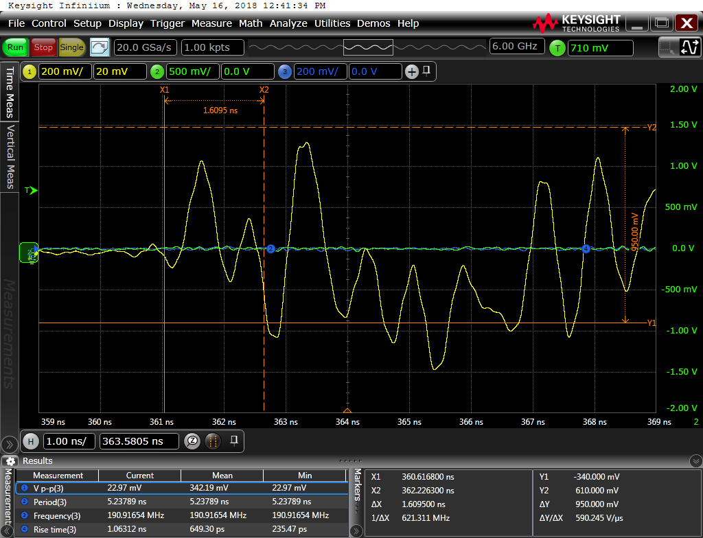
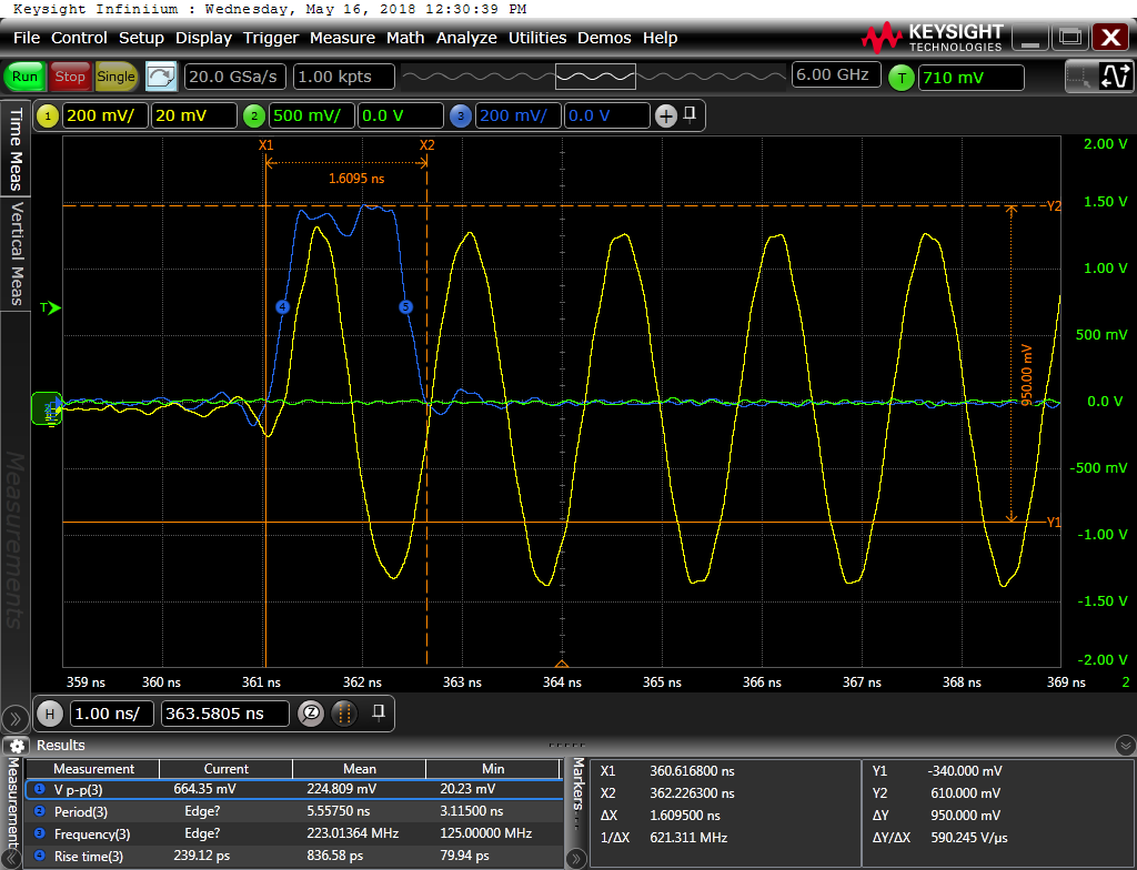
    I was not so successful with the trigger/ one-shot work.  I loaded the "narrow_pulse.csv" pattern you gave me, configured the HSDC Pro GUI for Software triggering, deselected "Trigger Continously" in  the DAC38RF8x GUI, and clicked on the "Generate Trigger" icon to send the "narrow_pulse" pattern to our 'scope (Agilent DSA90604A).  I had no problem repeatedly detecting the trigger signal from the "Trig Out C" port of the TSW14J56 pattern generator EVM, and triggering the 'scope with it.   What I did observe was that sometimes the DAC output  what I expected (see "narrow_pulse__good_trigger.png", attached), but more often than not the DAC seemed to output random garbage (see "narrow_pulse__bad_trigger.png", attached).   The purple trace is the DAC_B output, which is the sine wave contained in the second column of "narrow_pulse.csv".  The purple trace was either a coarsely sampled sine wave, or random garbage.  It is interesting to note that the "narrow pulse" channel (yellow trace) did NOT seem to generate random garbage.  When it worked, I saw the short pulse.  When it didn't, I basically captured a flat-line trace (i.e. zeros, like most of the 1st column in "narrow_pulse.csv"). 

    The latency between the rising edge of the trigger signal (output from TRIG OUT C) and the start of the narrow pulse was ~ 360 ns:  is this something that can be adjusted?  There seemed to be some minor variation in the exact delay between the trigger and the rise of the narrow_pulse/ blue trace, maybe on the order of 10's of ps.   What kind of repeatability should I expect in the trigger delay (+/- , in ps)?

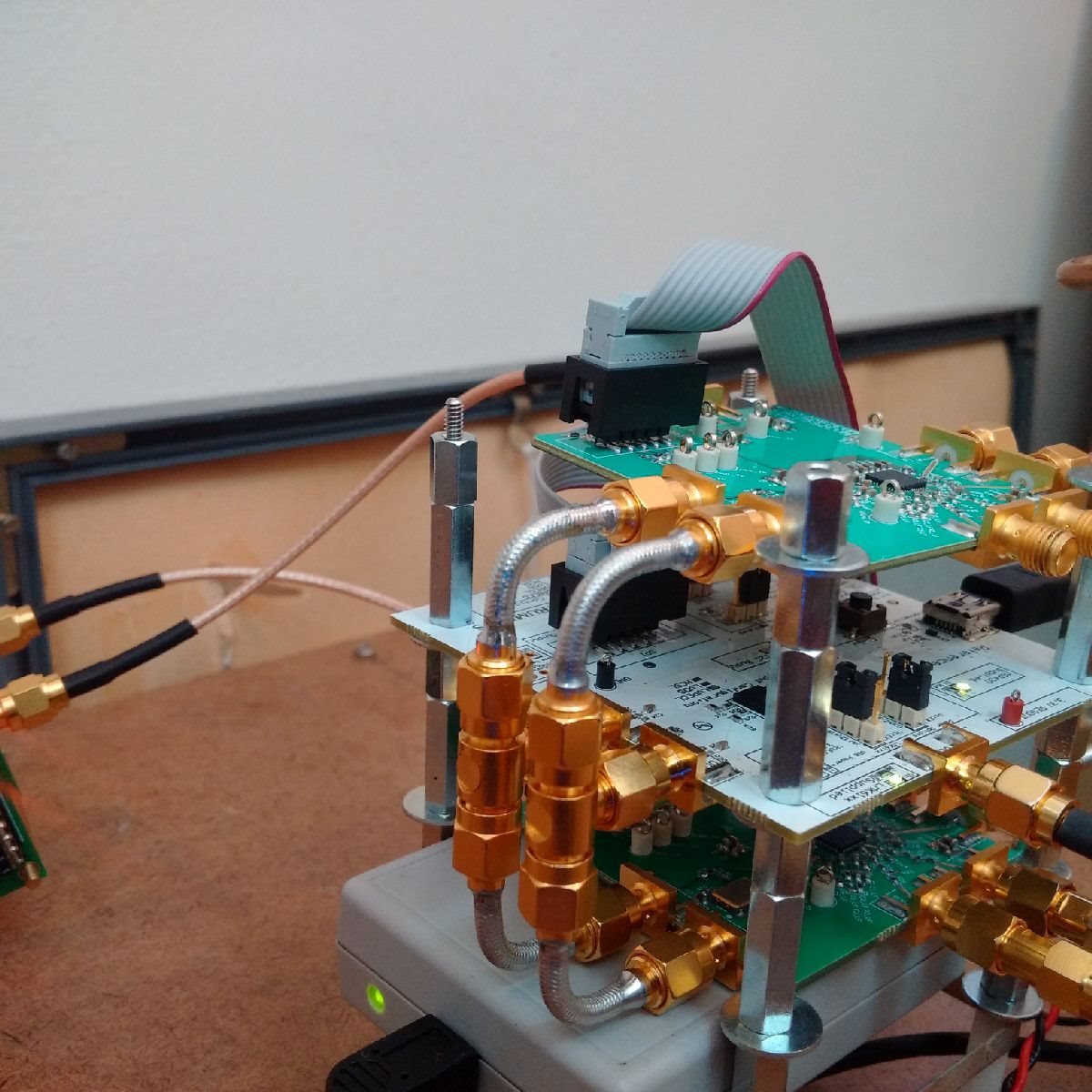
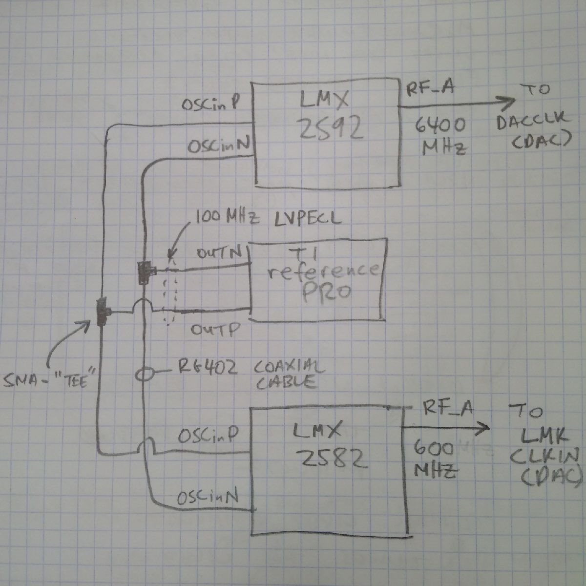
    I'm using an LMX2592 to generate the 6.4 GHz DACCLK signal, an LMX2582 to generate the 600 MHz signal for LMK_CLOCKIN, and a TI Reference PRO for the common Reference Oscillator signal (100 MHz, please see attached .JPG to understand our current "distribution" setup).  The DAC is operated in Dual DAC 12 bit mode, 2X interp, LMF_823 mode as described earlier in the thread. 

    I really appreciate your help with this issue, moving forward on our application requires reliable, precise triggering of the DAC .

    Much Thanks,

    -steve

  • Steve,

    I am checking with the firmware team regarding this.

    Regards,

    Jim

  • Steve,

    This from our firmware team:

    "We are looking at the inconsistency customer is seeing in DAC output and the issue can happen if there is any miss alignment in SOMF.

    Do you know if the issue happens only in SW trigger mode or in normal send as well, i.e. clicking SEND multiple times in HSDC Pro without trigger enabled?

    If there is any difference in behavior, it will help us debug further."

    Regards,

    Jim

  • Hi Jim,

    We also see the problem in untriggered mode, where we need to hit "send" multiple times to get valid output of the DAC.  I always thought there was something I was doing out of sequence in toggling between the DAC38RF8x GUI and the HSDCpro GUI.... until I started trying to use the trigger function.  Now it's apparent there's a problem with data alignment, in general.  Please keep me posted on what your team discovers.  We are nearing crunch time for our final hardware spec,  and resolving this issue will allow us to move forward in a big way.

    Much Thanks,

    -steve

  • Steve,

    We are seeing this issue in some setup cases in our lab. Are you using the GUI default value for "K" and SYSREF frequency?  Could you provide a simple block diagram showing the clocking scheme? It is hard to tell by the .jpg what is actually going where. There may be a timing issue due to your clocking scheme. For a test case, could you try another LMF setting like 821 and see if you have the same issues? This could help us trouble-shoot the issue. 

    Regards,

    Jim 

  • Hi Jim,

    Please find attached a pencil sketch/ schematic of our clock setup.  Sorry, time was at a premium today.... and I like graph paper.

    Every time I look at both clock signals on the scope, they look very stable/ no visible timing jitter between them.

    I did try the LMF821 mode, with the DACCLK=6400 MHz, LMK_CLKIN=400 MHz, Dual DAC Mode, Real, 4x interpolation.  I tried both a simple tone at 600 MHz, and our more complex waveform as an external pattern file.  I toggled between these two inputs about 3 or 4 times, and the output looked good/ as expected every time I hit send.  I never needed to toggle "DAC Reset JESD core and Trigger SYSREF" button on the DAC GUI.  So it seems like the LMF821 mode checks out, at least with the CLK frequencies I was using.

    Do you think there might be some benefit from having the DACCLK frequency (6400 MHz) as a 2^4 multiple of the LMK CLKin?

    I hope this helps, please keep me posted on your team's progress on the LMF823 setting (hopefully with the trigger working as expected).

    Much Thanks,

    -steve

  • Hi Jim,

    Any word back from your firmware team regarding the timing issues with the 12-bit/ Dual DAC LMF823 operating mode?  I neglected to mention in my last message that I'm using the GUI default values for "K" and the SYSREF frequency.

    We also encountered another, more subtle issue involving the power supplied to the DAC.  We were having some minor issues with the amplitude stability of the DAC output, so we looked at our 5V supply.  There was a bit of noise on the leads, so I soldered a 47 uF capacitor across the 5V test points on the DAC board.  When our chief scientist analyzed the output signals with the capacitor installed, he says the amplitude variations were greatly reduced.  Is there any concern that such a large capacitor across the 5V supply input could mess with the timing of the DAC board's power up sequence?  It seemed to "boot up" just fine after I installed the capacitor, but I don't want to jeopardize the hardware if you think this is a problematic solution.  Does doing a reset in the DAC GUI cycle the 5V power in any way?

    Thanks in advance for your help with this.

    Cheers,

    Steve

  • Steve,

    I was informed by our firmware team that the Altera IP currently does not support odd octets. We were informed this will be added but not until the end of the year. Our team did make some modifications to get this mode to work most of the time though. Problem is, when you start adding the trigger feature and attempt to synchronize two boards, it makes the task almost impossible. There is a chance this will work with the modifications described in the attached document. This will require a couple of changes to the DAC GUI settings and using a new ini file that is also attached. Please place this file in the following location on your computer:

    C:\Program Files(86)\Texas Instruments\High Speed Data Converter Pro\14J56revD Details\DAC files.

    Use this file when selecting the DAC in HSDC Pro.

    FYI,

    Odd octets is currently supported by Xilinx FPGA's.

    The DAC does not require power sequencing so your power fix should be fine. The reset does not effect the 5V supply.

    Regards,

    Jim

     DAC38RF8x_LMF_823_new.ini823 fix.docx

  • Hi Jim,

    Sorry for the delay in getting back to you.  I've been laid up fighting a virus my daughter was kind enough to share.  Back in action now, more or less.

    I tried the LMF_823 fix you recommended, by dropping in the modified .ini file and making the changes on the JESD sub-panel of the DAC38RF8x GUI.  Everything was input as you indicated in the .DOCX file... but for both Channel A and Channel B of the DAC.   In the JESD sub-panel screen shot you sent, Channel B was "greyed out" (suggesting you were operating in Single DAC 12-bit mode?).  We are trying to using the DAC in Dual Channel 12 bit mode, so I just applied the exact same field selections as given for DAC Channel A.  Please see attached .PNG file for details.

    I booted up and configured the HSDC Pro GUI as per usual, and tried to "SEND" a 1.35 GHz test tone (my usual starting input).  No blinking Tx LED on the TSW board, but I did turn on the "Tx_SYNS~" LED (D1).  I then reverted to the original .ini file, loaded my usual settings, and everything worked as expected/ as usual.  

    Is the addition of the second channel perhaps causing issues with the .ini "fix" file you sent?

    Maybe this is a good time to review what we're trying to do, and ask for your recommendation about how to best achieve the objective.  Especially in light of the recently discovered limitations with the Altera IP.

    WANTED:  Two Baseband channels:  Channel A to Tx "I" data , Channel B to Tx "Q" data.   BW ~ 1.4 GHz each  <== suggests an effective DAC rate of 3.2 GSPS:  we're currently running DACCLK=6.4 GHz, Interpolation = 2

    Aside from the Dual DAC 12 bit mode we've been working with, are there any other modes for the DAC38RF82EVM that meet our needs?   We are also open to the possibility of using a second DAC38RF82EVM, so long as we can tightly synchronize the two DACs via HW trigger.

    Any chance TI offers an EVM board based on an Xilinx FPGA chipset?

    Thanks, as always.

    -steve

  • Steve,

    I am afraid there is not much more I can do for you until Altera comes out with a fix for odd octet setups. I will be closing this ticket.

    Regards,

    Jim

  • Hi Jim,

    I fully understand your position, and I'm very grateful for all the help you've extended to me during our testing trials.  I did have a final question for you, regarding our end application.  Here's our  ultimate requirement:

    Two Baseband channels:  Channel A to Tx "I" data , Channel B to Tx "Q" data.   BW ~ 1.4 GHz each  <== suggests an effective DAC rate of 3.2 GSPS

     Are there any "even-octet" modes for the DAC38RF82EVM that meet our needs?   We are also open to the possibility of using a second DAC38RF82EVM....  so long as we can tightly synchronize the two DACs via HW trigger.   Any suggestions for synchronizing the DACs would be excellent.

     Much thanks,

    -steve

    PS:  I don't suppose TI will be releasing a "true" 12 GSPS DAC (6 GHz BW) any  time soon?  That would make life a LOT easier for designing the Tx chain of our application...

  • Steve,

    You could possibly get around 2GHz of bandwidth using the DAC in 82121 mode with the DAC sampling at 2500Gsps. The Altera firmware should not have an issue synchronizing two systems with this octet setting. If you send me your email address, I can send you info regarding future DAC's.

    Regards,

    Jim