This thread has been locked.

If you have a related question, please click the "Ask a related question" button in the top right corner. The newly created question will be automatically linked to this question.

ADS1291

Other Parts Discussed in Thread: ADS1291, ADS1292

I wonder if the ADS1291 is a released product. in the data sheet I couldn't find a note tell me which channel to use because 1292 has two channels. I guess only one of the two differential input channel will work in 1291, is it IN1P and IN1N? I feel frustrated when I read the datasheet and slau384.  did I miss the description of 1291 or the document forgot to put it in.

David

  • Hi David,

    Yes, it is a released product and channel 1 is what you would use for the ADS1291. Channel 2 becomes a no connect.

    Regards,

    Tony Calabria

  • Hello ,

    I have some questions about ADS1291 which i could not find the answers on datasheet.


    1)IN2N, IN2P, PGA2N,PGA2P,RESP_MODN,RESP_MODP

    Are these pins not connected or connected to some where?


    2)Are we going to use same register table with ADS1292. Is there also 12 byte register table?


    3)  05h CH2SET is exist but are we going to dont care?


    Regards,

    Fazıl

  • Hi Fazil,

    I understand the confusion, below are your answers -

    1. These are no connects and should be pulled high through weak pull up resistors.

    2. The register table does not change from the ADS1292 to the ADS1291. Register address 05h becomes dont cares but does still exist.

    3. See answer for number 2.

    Regards,

    Tony Calabria

  • Hello Fazl ;

    I am trying to use ADS1292 too ; could you share a working shematic please ; I have built a shematic but i am still need support.


    Thank you inadvanced

    Hector

  •  


    Hello Hector,

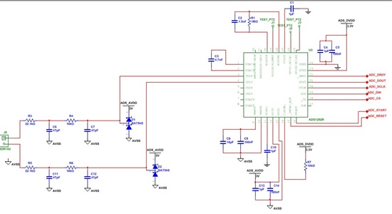
    i have used same schematics from ADS129X ECG Frontend Development board.

    In shematics i used ADS1291, but also if you use frontends shematic (from datasheet) it will work perfectly.

    If you send your own schematic we can discuss it.


    Best Regards


    Fazıl


  • Thank you fazl ;

    I will send you the shematic on friday ; I am out of the office travelling to UK; infact I am good digital one ; but not analog one :) .

    Do you have good experience with ECG analysis ?

    By the way your name sound Spanish ; are you ? I am spanish too .

    Regards

    Hector

  • Hi, Fazil

    I notice in your schematic you have a low pass filter with 66K cut off frequency. and in slau384, it also use a 66K cut off low pass filter, do you know why use a 66K cut off low pass.

    and I notice there is a 100K resistor between pin 29 to pin30 in slau384 for drive out feedback. do you use drive out in your design? if not, is R1 and C2 necessary?

    thank you for share your schematic.

    David

  • Hello David,

    This was my old schematics, now i changed some parts.

    66 kHz is only for reducing for unwanted noises, you can decrease the freq cutoff point to 2kHz levels by just changing the RC values, bu if you want to detect pacemaker activity do not set the value less than 20K Hz. I tried some R C combinations and get this result for ECG measurement.

    I place R1 and C2 for my other testings. I connected the 2 leads to PIN29 and PIN28 with 10M resistor and checked if baseline stability increases. (some small change with battery power supply)

     My primary applications is measuring ECG without a RLD. I noticed that if you want to get good ECG signal do not place extra components to ADS12xx but necessary components. Every extra component gives you a bigger noise than you expected.


    Fazil


  • Hi Fazil

    I know many portable or handheld device don't use RLD. if you don't have limitation of the application, do you think RLD will improve overall performance? ( baseline stability as you mentioned)

    Thank you 

    David 

  • Hello David,


    RLD is very useful in many ways. If you dont have any limitations you have to use RLD in biopotantials measurements.

    For further reading i suggest you to check out this application note.

    SBAA188


    Fazıl


  • thank you very much. 

  • Hi Fazil

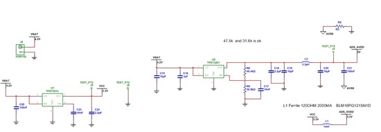
    I have one more question, in SLAU384, there are 3 Ferrite Beads used for VCC.  L3, L4 and L7 all used 0603 package Max current is 2A. for current in mA circuit is it really necessary to use that big margin. I hope I can use 0402 package which is 500mA rated.

    thank you,

    David

  • Hello, 

    I have one question about 1291 layout. there is no recommended land pattern pqfp32 in datasheet. in 1292 website there is an allegro package symbol, but my 16.2 dbdoctor couldn't upgrade it. I am not a professional layout guy. could anyone send a link or post an allegro 16.2 PCB editor symbol. appreciate your help.

    David 

  • Hello Tony Calabria, Fazil Duman, and Yuan-Heng Lu!
    I have followed this thread and the one where Lu shows his schematics, in my attempt to create a single-lead battery-driven low-energy ECG with rudimentary “patient-protection” based on ADS1291 and MSP430  micro controller. I would really appreciate if you, Tony, and anyone else would comment upon the schematic below. Will it work? What have I done wrong? What could be done better? I'm not an engineer by profession. I'm a surgeon but very interested in embedded design.
    As you can see I have left IN3N and IN3P unconnected. Can I use them for leads-on/off control? If they can be used for that purpose I would appreciate to get some directions about how to accomplish that.
    Further I want to kindly ask you, Fazil, to present your schematics in an other format. I have used .gif to present my schematics and I hope it will be easy to read. I have problems to read your schematics concerning your battery solution, which I find very interesting for my development. Thank you! Or  perhaps you can direct me to your source if you haven't developed them yourself.

    Regards Bo

  • >> 1. These are no connects and should be pulled high through weak pull up resistors.

    Does this mean that the unused pins on the ADS1291 are pulled high internally or that weak pullup resistors are required external to the pins?


    Thank you!

  • Tony was referring to external pull-up resistors. :)

    Regards,