This thread has been locked.

If you have a related question, please click the "Ask a related question" button in the top right corner. The newly created question will be automatically linked to this question.

ADS1299 lead off sense not being disabled.

Other Parts Discussed in Thread: ADS1299

Hi,

I have the ADS1299 gathering data and measuring impedance but when I switch from impedance measurements to data capture with the current sources disabled they still seem to be connected to the inputs, with no leads connected to the inputs the adc readings are all saturated where I would expect just noise.

To enable the impedance measurements I follow the following process.

 LOFF (0x04) set to 0x01

CONFIG4(0x17) set to 0x02 

LOFF_SENSP(0x0F) set to 0xFF;

LOFF_SENSN(0x10) set to 0xFF;

adc read started(Command 0x08)

To disable Impedance measurements, and change to data capture I am doing the following.

Stop adc reading(Command 0x0A)

LOFF (0x04) set to 0x00

CONFIG4(0x17) set to 0x00 

LOFF_SENSP(0x0F) set to 0x00

LOFF_SENSN(0x10) set to 0x00

adc read started(Command 0x08)

I have checked that each of the registers have been set by reading them back after they were set and they seem to be set correctly.

hope someone can help.

Graham

  • I also notice that reading the device ID returns 0x3E, should this be 0x1E?

  • Hi Graham,

    Thanks for your question. To start, I believe the Device ID 0x3E is ok. In this device, bits [7:5] are not used and they could be set to either 1 or 0 at production. The important bits to pay attention to are [3:0], which should read 1110 or 0xE.

    Do you have anything hooked up to the ADS1299 channel inputs? It sounds to me like they are just floating. Try shorting the PGA inputs internally or generating the internal test signal waveform to verify that the signal path is working properly.

    The lead-off current sources should not prevent you from acquiring data. They are often left ON while continuously taking data to monitor the lead connection status. Once you set the LOFF_SENSx bits to 0, the internal current sources are disconnected from the PGA inputs.

    Best Regards,

  • Hi Ryan,

    Thank you for your reply, If I have a signal generator hooked up to the inputs or the inputs are shorted, I get the output I would expect, but when I have nothing connected or just flying leads I would expect 50Hz noise which I do not see.

    this is only the case after I have enabled the lead off and then disabled it again, if I never enable lead off then I get the expected noise coming through the ADC.

    Regards

    Graham

  • Hi Graham,

    Where are you shorting the inputs: internally (using the MUX) or externally (using J6)? When you disconnect the leads and the inputs to the ADS1299 are floating externally, are they still shorted?

    I know that you shared your register configurations, which seem correct, but can you do an immediate register read after powering up the device and compare those settings with the settings you read after disabling lead-off? It's not immediately clear to me what might be different once lead-off is enabled and then disabled.

    Can you share an FFT (before enabling lead-off and after you disable it again) as well as a picture of your board showing your setup?

    Thanks and regards,

  • Hi Ryan,

    I am shorting the inputs externally, we are using a custom board with some additional protection components on the outputs, I doubt this would make significant difference though?

    I shall perform a read of all the registers now and do an fft and get back to you later today.

    Graham  

  • It looks like the registers read the same if lead off is never enabled and after it has been disabled, see debug printout below.


    Without impedance mode turned on


    Register 0x00 = 0x3E

    Register 0x01 = 0x91

    Register 0x02 = 0xC0

    Register 0x03 = 0xE0

    Register 0x04 = 0x00

    Register 0x05 = 0x50

    Register 0x06 = 0x50

    Register 0x07 = 0x50

    Register 0x08 = 0x50

    Register 0x09 = 0x50

    Register 0x0A = 0x50

    Register 0x0B = 0x50

    Register 0x0C = 0x50

    Register 0x0D = 0x00

    Register 0x0E = 0x00

    Register 0x0F = 0x00

    Register 0x10 = 0x00

    Register 0x11 = 0x00

    Register 0x12 = 0x00

    Register 0x13 = 0x00

    Register 0x14 = 0x0F

    Register 0x15 = 0x00

    Register 0x16 = 0x00

    Register 0x17 = 0x00

    With impedance mode turned on and off

    Register 0x00 = 0x3E

    Register 0x01 = 0x91

    Register 0x02 = 0xC0

    Register 0x03 = 0xE0

    Register 0x04 = 0x00

    Register 0x05 = 0x50

    Register 0x06 = 0x50

    Register 0x07 = 0x50

    Register 0x08 = 0x50

    Register 0x09 = 0x50

    Register 0x0A = 0x50

    Register 0x0B = 0x50

    Register 0x0C = 0x50

    Register 0x0D = 0x00

    Register 0x0E = 0x00

    Register 0x0F = 0x00

    Register 0x10 = 0x00

    Register 0x11 = 0x00

    Register 0x12 = 0x00

    Register 0x13 = 0x00

    Register 0x14 = 0x0F

    Register 0x15 = 0x00

    Register 0x16 = 0x00

    Register 0x17 = 0x00

    Checking these values, all were fine according to the datasheet, except bit7 in config3 should be 0 as we are using an external reference, I have changed this and it made no difference to the output.

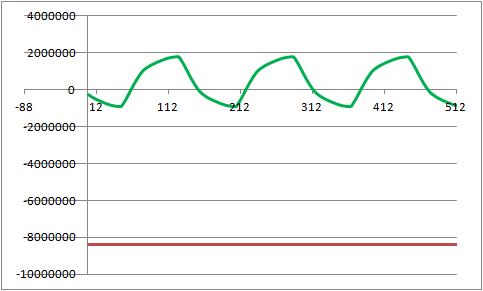
    Figure 1 shows the output from the ADS1299 Without impedance turned on and With impedance turned on and off.

    Figure 1: First 512 samples of data

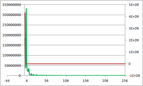
    Figure 2 shows the FFT of the above waveforms (performed using kiss-fftr) Without impedance turned on and With impedance turned on and off. Sample frequency is 8KSPS so FFT runs from 0 – 4KHz.


    Figure 2: FFT of first 512 samples of data

    Graham.

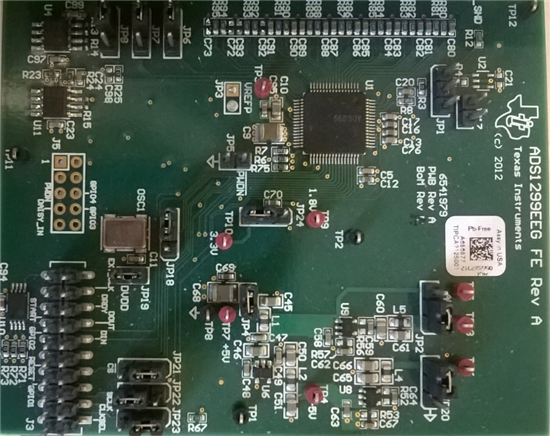
  • I have just tested this on our evaluation rig and that experiences the same problems, I have attached a photo of our jumper settings for this EVM.

    I have also tried shorting the channels internally using the mux settings and that behaves the same as shorting the inputs at J6.

    hopefully this will offer some clues.

  • Hi Graham,

    Thanks for sharing some more details.

    I will try to replicate this on the bench early next week using the same EVM. What concerns me the most is that you observed the full-scale output, even when doing an internal short. Whether the shorted inputs are driven or floating, an internal short should center the differential output around 0 again.

    Do the rest of the device configurations seem functional? (i.e. normal channel input, test signal, PGA and Data Rate settings, etc.)

    Best Regards,

  • Hi Ryan,

    the full scale output is observed when I have the inputs floating, with the inputs shorted (either externally or internally) I do get low levels of noise around 0.

    the other device functions seem to work, I am using PGA gain of 0 for checking supply rails and then changing to a PGA gain of 12 for data capture, changing data rate alters the frequency of the data ready signal.

    regards,

    Graham

  • Hi Graham,

    This makes more sense. When the inputs are floating, enabling the lead-off detection will pull the inputs high or low. When you disable the lead-off detection, the inputs do not have a path to discharge through. so the channel will remain at +/- full-scale until something is connected to the inputs. You might see the inputs discharge on their own through some leakage path after waiting awhile.

    Otherwise, it sounds like you are able to control the device settings properly.

    Best Regards,

  • Thanks Ryan,

    Would it be safe practice to short the inputs internally using the mux settings to discharge the inputs before going back to data capture?

    Regards,

    Graham 

  • Hi Graham,

    That should not be necessary for normal use. You can continue to capture data while lead-off detection is enabled (that is the way it is intended to work). As long as the inputs are not floating, the lead-off detection circuitry will not hold the inputs at the supplies.

    I suppose if your goal is to observe the 50Hz/60Hz noise with floating inputs, then you would have to momentarily short the inputs together after you disable lead-off detection to re-center the inputs to mid-supply. Is that what you were hoping to do?

    Regards,

  • Hi Ryan,

    Yes it required at the at the moment that we see the mains hum with floating inputs, I have just added a function to short the inputs temporarily and this seems to have fixed the issues I was seeing,

    Cheers.

    Graham

  • Further testing shows that this doesn't fully fix the problem, if I short the inputs internally then I get back data centred around 0, but if I short the inputs and then remove the short I still get a similar effect to what I was seeing before, although not always at the maximum full scale range. do you have any other suggestions / thoughts?

    Cheers,

    Graham

  • Graham,

    I am losing sight of what your goal is.

    When the inputs are shorted, and lead-off is enabled, the differential output is centered around 0V. Then you remove the input short so that the inputs are now floating, lead-off is still enabled, and the output goes near full-scale.

    That is the expectation of the lead-off feature. If you wish for the output not to be pulled high or low with floating inputs, then you must disable the lead-off detection feature. Otherwise, the inputs should be driven by some input voltage.

    Please let me know if something is still unclear or if I am misunderstanding your intentions.

    Best Regards,


  • Hi Ryan,

    Sorry for the delay replying.

    The issue I have is when lead off is enabled and then disabled.

    if the inputs are shorted and the adc values are read then I get low levels of noise around 0 which is expected.

    if the inputs are left floating and the adc values are read then the inputs are pulled to the full scale levels as expected from what you explained earlier.

    the desired goal for me is to enable lead off, check the status and then disable lead off, with the inputs floating I require to see mains noise.

    the last thing I tried was enabling lead off, disabling it again, shorting the inputs internally for up to 2 seconds and then removing the short and reading the adc values over 800 samples (0.1 seconds), in this scenario I would have expected the internal lead off circuitry to have discharged and the outputs to be close to 0 with mains noise present but although most channels (although not all) had reduced from the full scale range and there was some low levels of noise present, there was nothing that looked like mains frequency and the level which the adc values reduced was also random and generally much higher than the offsets observed previously on the same board.

  • Hi Graham,

    I followed a similar procedure on my bench, but things seem to be working correctly. I've shared the results in the .zip file below. As long as I disabled LOFF, shorted the inputs, and captured some data, the channel output was no longer saturated to full-scale. When data was captured with shorted inputs, the offset was about -26 uV, which is within the specification for PGA = 24 V/V.

    Perhaps that last part is where we differed - was the modulator converting and outputting data when the inputs were shorted?

    6747.ADS1299_LOFF.zip

    Best Regards,

  • Hi Ryan,

    No the modulator wasn't converting and outputting data when the inputs were shorted, I shall have to set this up and test it again once I have finished moving my SPI processing to DMA, I'll let you know the results.

    Regards.

  • Hey Ryan,

    Could you possibly share the settings and or software example which you used to get this working?

    Regards,

    Graham

  • Hi Graham,

    7635.ADS1299 Settings.docx

    The software that I was using to test this was the ADS1299EEG-FE PDK software, available here: http://www.ti.com/tool/ads1299eegfe-pdk. I simply changed the settings via the GUI, then re-acquired data (1000 samples at 250SPS).

    Before posting this, I repeated the same 5 steps on my EVM. The first try seemed to work. When I tried to repeat them a second time, the channel inputs seemed to be stuck at full-scale, even after disabling lead-off and acquiring new data with the inputs shorted.

    My conclusion would be that we need to take data for a longer period while the inputs are shorted together to fully discharge the inputs. The number of points needed to be collected will depend on the data rate, but for me it seemed to take at least 2500 samples at 250 SPS. Do you find that the inputs return from full-scale after increasing the number of samples acquired during an input-short?

    Best Regards,

  • Cheers for the help Ryan.

    I assumed it would just be a case of extending the time that the discharged, I extended it to 16000 samples @ 8KSPS which is far too high a delay for our application so I don't think extending that to 10 seconds would be a viable option. 

    Thanks anyway,

    Graham