This thread has been locked.

If you have a related question, please click the "Ask a related question" button in the top right corner. The newly created question will be automatically linked to this question.

ADS1148: Wrong calibration with SELFOCAL (and SYSGCAL)

Part Number: ADS1148
Other Parts Discussed in Thread: ADS1256, , ADS114S08, ADS1248

Hi

Are there some preconditions before executing the SELFOCAL command? I noticed when I am using an external reference and IDAC current, if the sensor (RTD in this case) is not connected, the calibration seems to fail, possibly because the reference is floating. When it happens, OFC registers get wrong values and internal temperature and voltage measurement (system monitor) is way off anything even remotely possible.

So do I need to set MUXCAL to 0b001 before sending the SELFOCAL command? Do I need to change REFSELT to use the internal reference?

And what about SYSGCAL? I don't have inputs supplying a full-scale input. But would setting MUXCAL to 0b010 be enough? Or I can't perform gain calibration at all in my setup?

For now I disabled calibration, since default values give acceptable results, but I would like extra precision if possible.

I should also add that I am used to the ADS1256 SELFCAL command, with which I never had any trouble.
I understand on the ADS1148 I need two commands to perform calibration, and that the gain calibration is not a "self" calibration command but is there any other difference?

thanks

  • Bobby,


    If you are running the SELFOCAL command, you do need the system to be operating normally (with a reference). The SELFOCAL command internally shorts the inputs together and takes a measurement. This measurement is subtracted from future measurements as the offset calibration. If you don't have a reference, then you don't have a good measuremnt of the reference.

    The SELFOCAL will automatically short the inputs together for you. You don't need to set the MUXCAL to 001 and you don't need to change the reference, but you do need the reference to be operating normally.

    For the SYSGCAL, you should be able to set the MUXCAL to 010 and run the command. It should calibrate the reference to the full scale value. However, I believe that you'll be under the max gain error spec of ±0.5%, without the calibration.


    Joseph Wu
  • OK so I should use the internal reference for calibration, since I can't guarantee the RTD will be connected (and therefore that there will be a voltage across my external reference during calibration)

    thanks
  • Bobby,


    That should be ok. The point of a gain calibration is to make sure that the input sampling and the reference sampling are calibrated against each other.

    Start with a SELFOCAL and the set the MUXCAL to 010 and run the SYSGCAL. Note that a large offset error will cause a bad gain calibration.


    Joseph Wu
  • So there is no point in performing the calibration against the internal reference? Which means I should calibrate only after detecting that my RTD sensor is connected so that a current flow through my reference resistance?
  • Bobby,

    Ideally you would want to run the calibration after detecting that the RTD sensor is connected. This would guarantee that the calibration is done while the ADC is running in the mode you are using it.

    I think that running a SYSGCAL with a different reference might offer a slightly better result than no gain calibration. This attempts to calibrate the input sampling against the reference sampling. However, the offset error difference from one reference to the next reference may add to error in the gain calibration.

    Again, I think you'd want to run the calibration after detecting that the RTD sensor is connected.

    Joseph Wu

  • Hi Bobby,

    would you have the possibility in your design for calibration purposes to route the IDACs in such a way that they excite the reference resistor even when an RTD is not connected? That way you could create a valid reference voltage.

    In general we would recommend to connect a precision resistor to simulate an RTD while you run a gain calibration. That way you also calibrate the error caused by the external reference resistor. If you use a precision resistor that is equal to the maximum RTD value that will occur in your system, then you might be able to use the SYSGCAL function for that.
    Otherwise we would recommend to implement the gain calibration routine in your processor, because the SYSCCAL function only works when applying a full-scale signal.
    It should be sufficient to run the gain calibration one time when your system leaves your production line.

    Regards,
  • Hi Joachim,

    I do not currently have that possibility, we may add it in a next PCB revision on the unused AIN7 input.

    Even when calibrating (SELFOCAL + SYSGCAL) using our external reference with the excitation current turned on, the result seems off (further away from the expected result).

    When connecting a 110 Ohm 0.1% on one of the RTD inputs, with a gain of 8 and IDAC1 current of 1.5 mA, I measure 163.7 mV on the RTD and 2.381 V on the 1.6 kOhm reference  using a multimeter. 0.1637/2.381*8*32767 = 18023

    The ADC gives me a decimal output code of 18065, which is 0.23% over my expected result. Do you see a problem with my design?

    Without calibrating the result is spot on, but perhaps this is a coincidence.

    thanks

  • Hi Bobby,

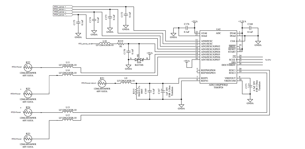
    thanks a lot for sharing your schematic. It is not 100% clear to me how your RTDs would be connected to RTDx-Power, RTDx_sense+, RTD_sense_ret and RTD-Power-return. And what type of RTDs are you using (2-, 3-, or 4-wire)?

    In general I would like to see RC filters on all measurement inputs.

    Without gain calibration you primarily need to account for three gain error sources (at room temperature):
    - gain error of ADS1148 (up to 0.5%)
    - accuracy of RREF (up to 0.1% in your case)
    - accuracy of RTD simulation resistor (up to 0.1% in your case)
    Over temperature you would then also have to account for the drift of all those errors.

    When you perform a SYSGCAL where you use the reference inputs as the inputs to the ADC (MUXCAL[2:0]=010) then you calibrate the gain error of the ADS1148 but not the error introduced by the RREF. In addition the MUXCAL[2:0]=010 setting changes the gain to 1. Means you are not calibrating the setting for Gain=8.
    (That is for example one reason why I don't offer this MUXCAL setting in the successor device of ADS1148 , called ADS114S08, anymore).

    My recommendation would be to run a SELFOCAL while you have a valid external reference connected and then perform a gain calibration yourself in the MCU. For that you would connect a precision resistor with a value in the upper range of the RTD values and then simply calculate a gain correction factor. You could in principle store this gain correction factor in the ADS1148 FSC register then.

    Regards,

  • Hi

    We are using 4-wires RTDs.

    We sense between RTDx_sense+ and RTD_sense_ret.

    IDAC current flow from RTDx-Power to RTD-Power-return.

    The gain error seems to be the largest source of error in this case. I calibrated using MUXCAL=010. I knew the gain would change to 1, but I assumed it would be better than not calibrating at all?

    I could use AIN7 to connect a fixed precision resistor in next revision. Can the pin serves both as an IEXC and AIN7 at the same time?

    The maximum resistance we can measure is 200 Ohm. Should I use that value in order to read 0x7FFF, or should I use a slightly lower resistance value for gain calibration?

    thanks

  • Thanks Bobby. I see.

    Please apologize my additional questions but for my own interest, why did you only place an RC filter and diode protection on RTD_sense_ret but not on the RTDx_sense+ inputs then?

    Yes, AIN7 can be used as an IEXC output and at the same time be configured for measurement.
    However, as mentioned earlier, I would simply run an end-of-line calibration in your production and connect a precision resistor externally during that calibration. That saves you having to place another precision resistor on each board. You would save the calibration coefficients in your MCU Flash or EEPROM then.

    If you want to use the SYSGCAL function, then you should connect a 200 Ohm resistor.
    In case you want to run your own gain calibration routine in the MCU as I recommended, then I would probably use a value around 190 Ohm. The gain correction factor would then be derived by comparing the measured code with the ideally expected code.

    Just FYI: The ADS114S08 that I mentioned in my previous post will release to market in June. This ADC would offer more analog inputs so that you could connect one differential analog input pair to each RTD. Plus the ADS114S08 has a much tighter gain error specification. In this case the external RREF would limit your overall system gain error.

    Regards,
  • Hi Joachim,

    Good question, would you recommend adding a RC filter as described in this document www.ti.com/.../sbaa201.pdf ?
    I would say we are satisfied with the stability of the reading, but it would be great if we can fix what seems to be the gain error.

    We will first try gain calibration using a 200 Ohm precision resistance, and then will consider whether we add the ~190 Ohm precision resistance to the next revision.

    Just so that I fully understand how SYSGCAL works, what would happen if I were to use a 201 Ohm (or greater) resistance with a gain of 8? The input would saturate to 0x7FFF but would the calibration result be valid?

    Another question, could I use the +5VA on AIN7 to perform a more precise offset calibration than with SELFOCAL? By selecting both P and N channels to be routed to AIN7? Or if it's important to be close to mid supply?


    thanks
  • Hi Bobby,

    I would in general recommend RC filters on all analog inputs. They do not only act as anti-aliasing filters but also as current limiting resistors to protect the analog inputs in the event of an overvoltage.
    I am not sure if it is that critical to match the RC filters between the analog inputs and reference inputs as described in the application note with a 16-bit ADC.

    Let me discuss your SYSGCAL question with Joseph tomorrow. I think that should work fine even with a 201 Ohm or larger resistor because the delta-sigma modulator does not saturate yet when you apply a full-scale signal. After the SYSGCAL you would simply find a gain correction factor <1 in the FSC register.

    I would not recommend connecting AINP and AINN to AIN7 in your case. Main reason is that you are operating the PGA outside its linear operating range in that case. Using the internal short to mid-supply would be just fine.
    The only better option would be to place a short between RTDx_sense+ and RTD_sense_ret and run a SYSOCAL. That way you would also calibrate any offset voltages in your external signal chain, e.g. voltage drops across the filter resistors.

    Regards,
  • Bobby,


    I haven't had a chance to discuss this issue with Joachim yet, and I'm still reading through the posts from the weekend. However, I did have a few comments to add to the discussion.

    For your setup, I would first look to see if bypassing the ferrite beads will reduce the amount of error in the measurement. Many people use them, but with the digital currents seen while periodically sampling the inputs or the reference, there may be a voltage spike from the Ldi/dt. This might disrupt the sampling, but it's likely going to be a very small effect.

    There may be some leakage current associated with the BAT54S. It's probably less than 0.1uA, which may be seen from the RTD_sense_ret line as it reacts to the 1kΩ series resistance. It may not be a lot, but check it so that we can rule out this error as a contributor.

    You should also measure the reference voltage and the input voltage with a precision multimeter. The Agilent 34401A multimeter (or similar) would likely have a good precision and linearity if you stay in the same range. It would verify the gain error based on what the ADC sees and you could confirm the gain calibration. Relying on the precision of the resistors might be problematic if you have any extra series resistance. You could use different values of resistors to determine if the error is a gain error or an offset error. I'd also point out that it's important to have test and reference resistors that have a low drift as well . You want to make sure that as the currents are applied, the self heating in the resistances are not a factor.

    Lastly, I would try to put the board in a metal enclosure, just to make sure there isn't any errors from EMI. I've seen EMI affect gain error and offset. If you have large lengths of wire for the input or the reference, it could be a problem.

    Joseph Wu
  • Hi Joseph

    Thanks for the suggestions. We already tried removing the BAT54S, and didn't notice a difference. I should say we only need precision of about 0.1 °C.

  • Would using the ADS1248 instead give us better performance even if we don't need 24 bits? Is the ±0.02% maximum gain error before or after calibration?

    thanks
  • Hi Bobby,

    the ADS1248 would offer better performance than ADS1148 if you don't run any SYSGCAL.
    The individual gains in ADS1248 are factory trimmed to meet the max gain error of 0.02%. Means this is before any user calibration.

    Alternatively you could use the ADS114S08 as I mentioned before. In this device the max gain error without any user calibration is 0.012% and you have the benefit that you could use a differential input pair for each RTD.

    Regards,

  • The ADS114S08 would be better, but the ADS1248 seems to be fit form and function with the ADS1148 (as we can read only the first 16 bits) , and this is a major advantage for us at the moment.

    thanks

  • Yes, that is certainly true.

    Regards,