This thread has been locked.

If you have a related question, please click the "Ask a related question" button in the top right corner. The newly created question will be automatically linked to this question.

ADS124S08: Scaling error in 4-wire RTD measurements

Part Number: ADS124S08

I am using the ADS124S08 to do a 4-wire RTD temperature sensor measurement.  The measurement that I am reading out from the device after a conversion is consistently off by ~1% of the value under test.  For instance, a resistance of 50 ohms is read as ~50.5 ohms and a resistance of 150 ohms is read as ~151.5 ohms.  The test setup uses calibrated RTD simulators that we have independently verified to be accurate.

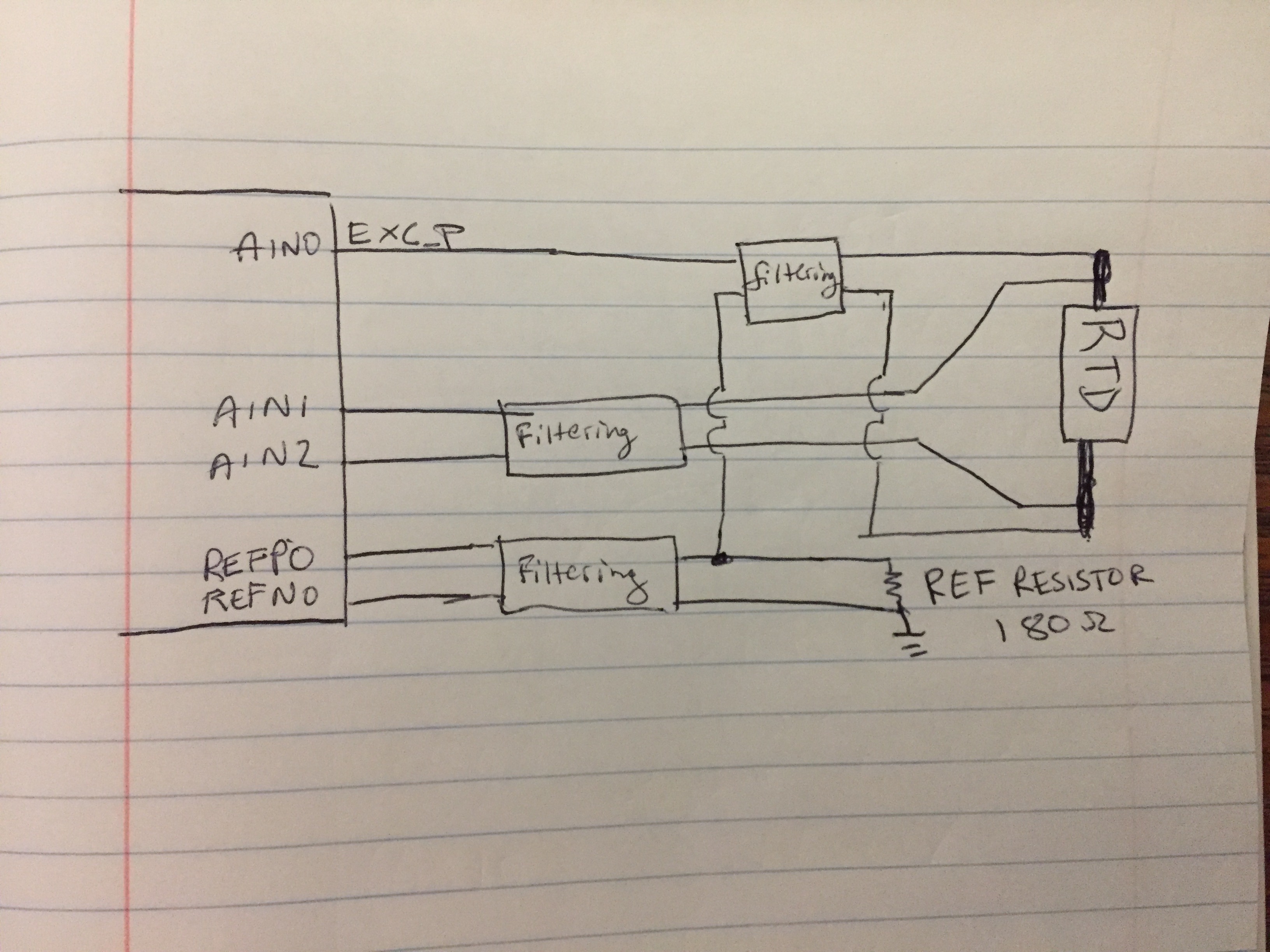
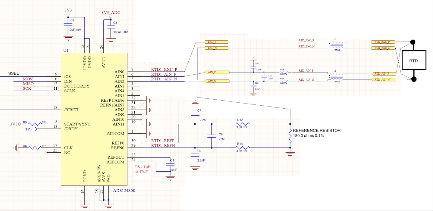
The general setup includes an excitation current on AIN0 with measurement on AIN1 and AIN2.  There is also a reference resistor in series with the measurement resistor with the reference REFP0 and REFN0 being used.   The reference resistor used is a .1% 180 ohm resistor.  This can be seen in the schematic below.  

My initialization of this device includes setting the following registers and commands:

  • Command RESET
  • Check for Device Ready Flag in the STATUS reg
  • IDACMAG-> 06h (sets IDAC magnitude to 750uA)
  • REF-> 22h (disable reference monitor configuration, disable positive reference buffer bypass, enable negative reference buffer bypass, reference input selection (REFP0/REFN0), internal reference always on)
  • IDACMUX-> 0fh (IDAC2 output - AIN0, IDAC1 output - disconnected)
  • INPMUX-> 12h (positive ADC input - AIN1, negative ADC input - AIN2)
  • Command START

My problem is trying to eliminate this 1% error in my readings.

Thank you for any feedback,

Eddie

Idealized schematic:

Simplified actual schematic:

(Please excuse this crudely, Paint-edited schematic!)

Register configurations:

  • Hi Edward,

    Welcome to the forum! A couple of general comments first.  When looking at the ADC accuracy you need to consider all other possible inaccuracies.  Often times eliminating many of these inaccuracies will require some sort of calibration to eliminate offset and gain errors.  It is always a good idea to run the self offset calibration after device configuration.

    The reference resistor can drift, so this error must be taken into account.

    You show using 180 ohm reference resitor with 750uA of current.  This gives a reference voltage of 135mV which is outside the reference specification.  The minimum reference is 500mV.

    Even though the PGA is disabled in your settings you should use the PGA along with some gain.  Take a look at the specification for the Analog Inputs on page 7 of the ADS124S08 datasheet under Absolute Input Voltage.  For a gain of 1 with PGA enabled the input voltage must be greater than 0.15V.  Currently your reference resistor places you at 0.135V which would be too low for using the PGA.  If you increase your reference resistor you should also be able to increase the gain which will help lower the input referred noise.

    You should change C3 from 100nF to at least 330nF at the AVDD pin.

    Best regards,

    Bob B

  • Hi Bob,

    Thanks for the reply and the help.

    The RTD values that we are trying to measure ranges from approximately 52 ohms to 150 ohms. Knowing these values what reference resistors should we use? Is their a recommended ratio between the size of the resistor we are measuring to the size of the reference resistor?

    Also, could you also elaborate on why you recommend the change to C3?

    Thanks,
    Eddie
  • Hi Eddie,

    The recommendation regarding the bypass cap on AVDD is given in section 11.4 on page 97 of the ADS124S08 datasheet.

    I would also suggest looking at the application section regarding the 3-wire RTD.  This is in section 10.2 on page 90.  Many similar considerations are given even though 2 current sources are used.  Your circuit is actually a little less complicated in that you are using a low-side reference eliminating the need for a bias resistor and a reference resistor.

    Generally you target the RTD common-mode to be about 1/2 of the AVDD supply which would be in the neighborhood of 1.65V.  If you used a 2k resistor with 750uA you have a reference voltage of about 1.5V.  If your maximum input voltage is 112mV, then you could use a gain of 8 for the PGA.  This may be a good starting point, but you could try adjusting the reference resistor up or down to get the best dynamic range.

    There is a design calculator available on TI.com for download to help with these calculations:

    http://www.ti.com/lit/zip/sbac158

    Best regards,

    Bob B

  • Hi Bob,

    I ended up swapping the 180 ohm resistor for a 1.8 k ohm 0.1% resistor that I had on hand. This brought the reference voltages into the proper range; though the inaccuracies still persisted.

    We noticed a rather large voltage drop (16mV) across the resistor R12 in the filter, but a reasonable 8 uV across R14. Looking at the data sheet we noticed that the negative reference buffer was disabled and the positive enabled. We swapped the enable and disable for the reference buffers so the configuration matched the default configuration. This caused the large voltage drop to appear across R14 and a reasonable voltage drop to appear across R12. At this point, shorting R14 made the measurements reach the accuracy that we expected.

    We tried one more thing, we enabled both the positive and negative reference buffer bypasses (\REFN_BUF and \REFP_BUF) this eliminated the inaccuracies as well. So, we're in good shape as far getting the accuracy that we expected.

    My one question remaining is the negative reference buffer bypass is recommended to be disabled when V_REFN is close to AVSS:
    "Disables the negative reference buffer. Recommended when V(REFNx) is close to AVSS." (p 77)
    Do you know why this recommendation is made? We seemed to see that both needed to be enabled to get the accuracy we expected.

    Thanks for the help,
    Eddie

  • Hi Eddie,

    Notice on page 10 of the ADS124S08 datasheet the Voltage Reference Inputs section at the top of the page.  Here you can see the differences you are seeing in relation to turning on and off the buffers. So you are definitely at an advantage by using the buffers if possible.  You should for sure enable the REFP buffer.

    When using semiconductor materials it is difficult to drive close to the supply rails.  To maintain performance and linearity throughout the entire operating range of the ADS124S08, it is advised to turn off the buffer when operating close to the supply rail.  This may be of greater concern when operating from an externally supplied reference source.

    Your options are to use a smaller resistor for R14, remove R14 altogether, or turn on the reference buffer for REFN.  There are pros and cons to each method.  My suggestion would be to leave R14 and populate with a 0 ohm resistor and operate with REFN buffer off.  If there are issues with ground noise in your testing you could always populate R14 with a higher value to add some filtering.  I would turn on the REFN buffer if all else fails to perform.

    Best regards,

    Bob B