This thread has been locked.

If you have a related question, please click the "Ask a related question" button in the top right corner. The newly created question will be automatically linked to this question.

ADS1299: ADS1299 Wrong Voltage References

Part Number: ADS1299

Hello,

I have been trying to use the ADS1299 (6 chanels), but I am having some trouble. The voltage on the VREFP and VCAP pins seems to be wrong, and I am getting some noisy and wrong data. 

The voltage on VCAP1 is 900mV and on VREFP only 100mV. 

The registers are configured as (Python)

self.SPI_writeSingleReg(REG_CONFIG3, 0xE0)

self.SPI_writeSingleReg(REG_CONFIG2, 0xD0)

tx_buf = [0] * self.nb_channels
for i in xrange(0, self.nb_channels):
tx_buf[i] = 0x65
self.SPI_writeMultipleReg(REG_CHnSET_BASE, tx_buf)

I don't know what to do to get the proper voltages. I have already tried to change the capacitors  for some new ones.

  • Hello Felipe,

    Thanks for your post and welcome to the forum!

    Are you implementing this discretely or using the EVM? If discrete, can you post your schematic?

    As mentioned in the pin functions section of the datasheet:
    Do you have a 10uF capacitor between VREFP and VREFN?
    Do you have capacitors to AVSS from your 4 VCAP pins?

    Since square waves contain signals of all frequencies, sometimes it is helpful to input a sine wave that you know is within the pass-band of your input RC filter. Does the problem still occur when using a sine wave?
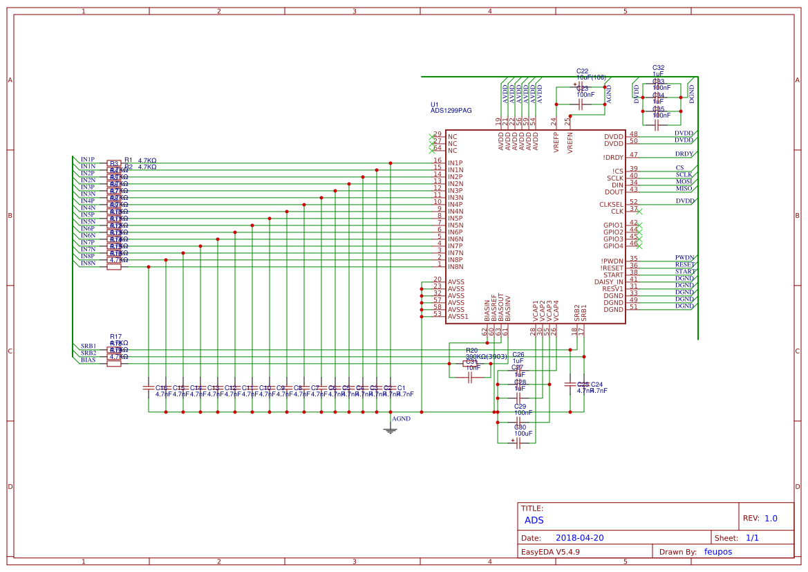
  • It is discrete, but is mostly based on the EVM itself. I do have a 10uF capacitor between VREFP and VREFN. Here is the circuit: 

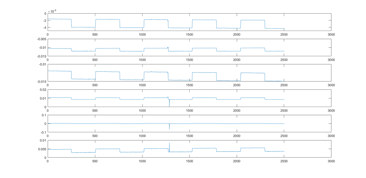
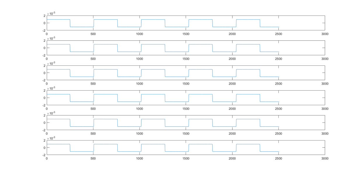
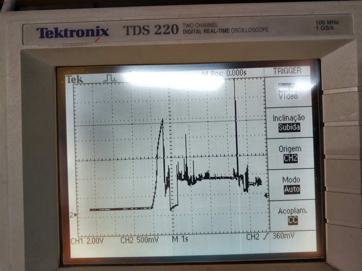
    But I have some updates to my issue. Sometimes I have noticed the ADS1299 will only send zeros, no matter the input, and it seems to be random. Also, I was able to measure the test signals properly, but only a few times after I turned my circuit on. Here is the sample just after startup:

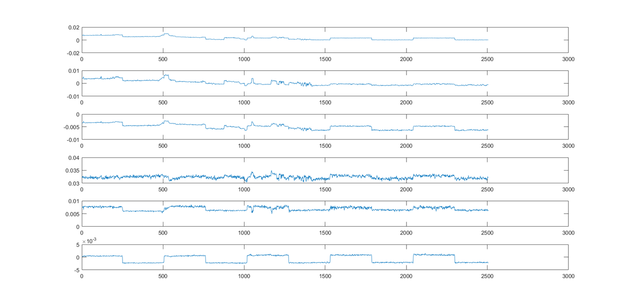
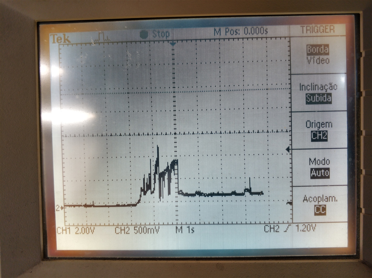
    And this is 30 minutes after using it a couple times:

    I have already tried changing my capacitors, even using other types, such as electrolytic. 

    Also I have tried to measure a square wave generated by a function generator. I was able to get the sample only a few times before it stopped working again.

  • I have also been trying to measure the voltage on the VREFP pin with the oscilloscope but I am only getting around 400mV
  • Hello Felipe,

    Thank you for providing your schematic and additional information.

    Will you please provide your full list of register settings?

    It is interesting that the data gets worse over time as the circuit remains on. When you power cycle the circuit does the output revert to what is seen in the first image?

    Are you reading data in RDATA or RDATAC mode? How many SCLKs are you sending for each new data sample?
  • Thank you for your support.

    It is operating in RDATAC, at 500sps.
    It usually only goes back to normal on the next day, after leaving it disconnected.

    I have also tried to use external power supplies, but with the same results.

    I am not in my laboratory now, so I will only be able to send you the information about the registers tomorrow.
  • I have checked the registers, it is as follows:
    MISC1 = 0x20
    BIAS_SENSN = 0x00
    BIAS_SENSP = 0x00
    CONFIG1 = 95
    CONFIG3, 0xE0

    For test mode:
    CONFIG2 = 0xD0
    CHnSET = 0x65
    For reading input:
    CONFIG2, 0xC0
    CHnSET = 0x60

    I was able to get a few samples on a sine input, but it seemed to be heavily attenuated, because my input signal was around 2Vpp and it did not saturate the inputs even with 24x gain on the PGA.

    The code that I am using is also available here: github.com/.../ADS1299_API.py

    I think it might be necessary to test the board with another IC to see if there is a problem with this one but I don't have another one available now.
  • Hi Felipe,

    Thank you for providing the register settings. Were these taken after the device powered up initially or later on? I would like to verify that they are not changing with time.

    I think that the data is being corrupted due to reference collapse.
    Can you take a falling edge oscilloscope shot of your reference voltage collapsing?

    Testing with a new IC to confirm would be helpful as well, but I'm not positive that it is an IC issue yet.
  • These are the values that I have set after startup, they are re-written at every measurement cycle.
    I will try to read directly from the IC to see if it is changing.

    The voltage reference you mean the VREFP pin, right?? It is only reaching 400mV. I will try to capture it as soon as possible.
  • Thank you Felipe.

    Yes I do. It should be at 4.5V, so if it is only getting to 400mV that is concerning.
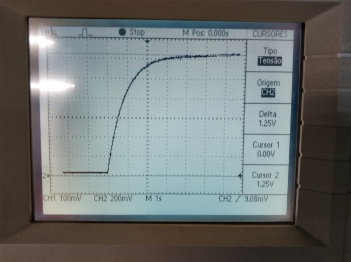
  • I have got a couple of shots of the VREFP pin, it is really concerning. I have even tried changing the capacitor .

    This would explain why I can get samples of the test signal, but the input signals appear attenuated.

  • Hi Felipe,

    Since your reference is having issues it will be impossible to get any sort of meaningful data from the device. I'm honestly surprised that you were able to get the test waveforms back as clean as they currently are.

    Were these taken from power up or after writing registers and enabling the buffer?

    Can you capture the reference after it has ramped to full scale to see the collapse?

    Give the device a little bit of time after power up before measuring and just a side note, you do not need to re-write the registers every cycle.

  • These measurements were taken from power up and until after writing the registers and starting to record data. The signal is connected on the oscilloscope channel 2.

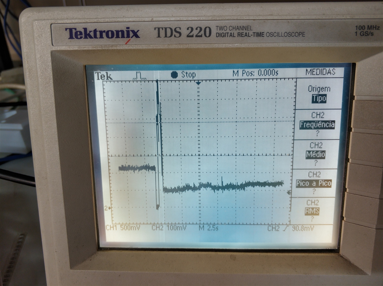
    This is another shot I took right now. The device is previously powered up, and then I reboot cycle it, write the registers and wait for 5 seconds until starting RDATAC mode. The voltage is never able to reach the expected value, it looks like it tries to reach but fails and then settles at a very low voltage

     .

  • I have also been trying to get some new data samples, from the test mode and external generator, but for the last couple of minutes the device is only sending me zeroes. I guess I will have to wait until tomorrow for it to start working again.

    Besides VREFP, are there any other voltages I should be concerned that could be causing this weird behavior?
  • Thank you Felipe, that's exactly what I was looking for.

    Are your power supplies connected and behaving as expected?

    Is it possible for you to connect an external reference voltage?

    Do you have another device you can test to confirm that the current device under test is not damaged?
  • Thank you for your support so far.

    Yes, the power supplies are fine, I have checked the voltages and even connected external power supplies to see if they could be the problem.

    I tried connecting an external reference of 4.5V, the test signals appeared offset and very noisy. When I tried to acquire an external signal the device started outputting only zeroes, and did not come back to normal. It happened before, and last time I had to leave it for a day until it started working back again.

    Unfortunately this is my only device.
  • Hi Felipe,

    To test the device to see if it is still functional, power it on and test VCAP to see if it gets up to 1.1-1.2V. Do not write any registers, do not try and send data to the device. If VCAP is not getting to 1.1-1.2V then something is either wrong with your supplies or the device is damaged.

    Unfortunately this is a last resort in the debug process.
  • I have measured VCAP with the oscilloscope, it raises up to 1.2V as it should, and does not drop during operation.

    But unfortunately the VREFP seems to be the cause of the problem, I have tried to put the external voltage reference, but upon doing so, the device will only output zeroes, so I am figuring that this pin is definitely the problem here, I have double checked all the pins for shorts and verified the proper connections, and everything seems to be OK, so it appears to be an internal problem, but I have no clue what could be the cause, maybe there was a defective capacitor initially, but I have also changed all the capacitors of the board, and changed from tantalum to electrolytic also for testing purposes. But I guess there is no hope in getting this IC to work.

  • Hi Felipe,

    VCAP correctly charging is very good news. Do not lose hope!

    When you applied an external voltage reference, did you enable the external reference in the register settings?

    I do not think the external capacitors are the problem, but of course it is possible that the pin has been damaged in some way from an ESD event. 

  • Yes, I did enable the external voltage reference, by setting 0x60 on the CONFIG3 register. Is there anything else I should be doing?

  • No, that is correct. What are you measuring on the VREFP pin when you apply the external voltage? Is it being driven to ground or remaining stable?
  • It remains stable, but it is a regulated power supply, the voltage is stable at 4.5V, I checked it with an oscilloscope, and it shows as the circuit is draining around 5mA.
  • in case it is really the IC problem, do you think it would be possible to send a spare so I could assemble a new board for testing?

  • Hi Felipe,

    Is it alright if I contact you offline at your registered email address?
  • Hello,

    I am sorry it took me very long to reply, but I finally managed to assemble a new board. 

    With this one now all the voltages are correct, VCAP1 reaches 1.2V and VREFP is at 4.5V.

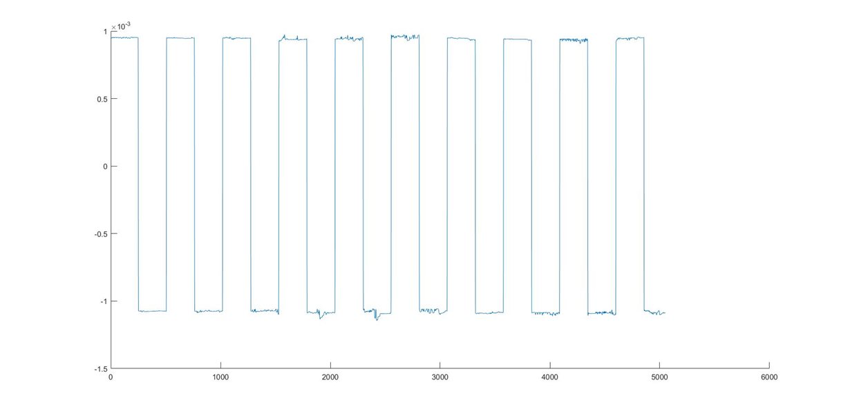
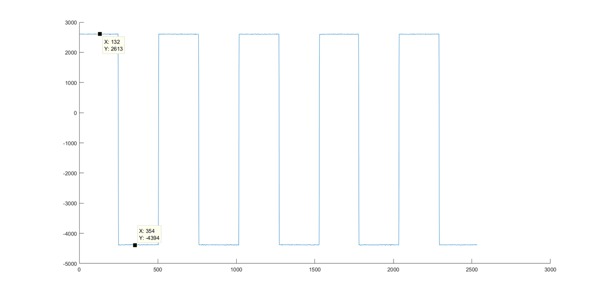
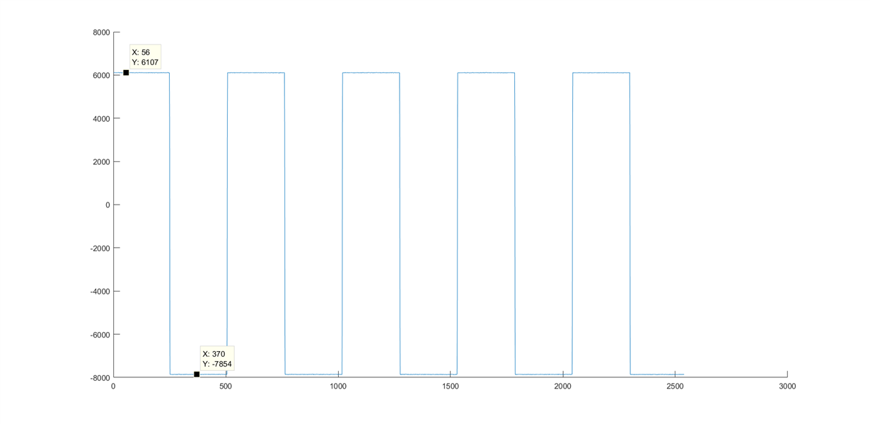
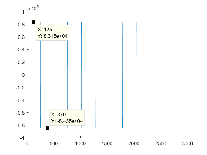
    Now I have another question regarding the test signals, where I can get stable readings and the amplitude looks correct considering REG_CONFIG2, 0xD0, but I noticed that the positive and negative swings are different with different gains. Is is superposed to be like that? Is the test signal referenced on (VREFP-VREFN)/2

    These are some shots from channel 1 with gains 1,2 and 24 reading the test signal.

  • Hello Felipe,

    I'm happy to see that the board has been assembled!

    This could be a 2's complement conversion issue. Try using a known input signal in "normal electrode" mode and see if the result matches the input. Looking at the binary output from the ADC and seeing if it matches the code would work as well.