This thread has been locked.

If you have a related question, please click the "Ask a related question" button in the top right corner. The newly created question will be automatically linked to this question.

Flashing TMS320F28335 through JTAG interface

Other Parts Discussed in Thread: TMS320F28335

Dear all,

we would like to flash TMS320F28335 using JTAG interface. however on FLash API documentation, there is the following statement:

For programming the device through the JTAG port, use the SDFlash programmer from TI 3rd Party vendor Spectrum Digital Inc. (www.spectrumdigital.com) or the Code Composer StudioTM (CCS) Plug-in. Check the TI website, and CCS update advisor for updates to the plug-in to incorporate this version of the API.


Has anyone documentation about how to do it or where to find it?

Any help will be highly appreciated.

Best Regards,

Samuele Stefanoni


  • Samuele,

    There are various methods that can be used to flash C2000 devices:

    1)  During development you can use the Code Composer Studio IDE to flash the device.  This allows you to program the device and easily be able to debug your code as a next step.  CCSv4 and CCSv5 have the ability to flash a device embedded into the IDE.

    2)  If you are interested in a factory programming solution with JTAG, we recommend going through a 3rd party solution.  There are various 3rd parties that offer this type of solution either to program individual chips or multiple at one time.  A few are:
       - Blackhawk-dsp
       - Elpotronic
       - Spectrum Digital

    3) If you already have an emulator and would like an easy-to-use programming solution with JTAG, I would recommend C2Prog by CodeSkin.  The software is free and they can customize the program for your solution.


    Thank you,
    Brett

  • Hi Brett,

    thank you for your reply. We actually develop 3rd party solutions for ISP programming, so my goal is to find out programming specification through JTAG interface.

    Can you help me finding this kind of documentation?

    Best Regards,

    Samuele Stefanoni

  • Samuele,

    I've moved your post to the Code Composer forum.  This would be the group that would be able to help with your request.


    Thank you,
    Brett

  • Hi Samuele,

    this wiki might be a good place to look for further information and documentation.

    http://processors.wiki.ti.com/index.php/Category:Emulation

    You can also find useful information on the C2000 wiki as well.

    http://processors.wiki.ti.com/index.php/Category:C2000

    TI devices comply to the IEEE JTAG standard, however some devices do not have a full implementation (for example the MSP430 family does not support boundary scan). (What is implemented is compliant)

    I hope this helps.

    Best Regards,
    Lisa

  • Samuele,

    Are you developing your own JTAG probe that would do the flash programming or would you be using an XDS emulator of some sort?  If you are doing your own probe then you are likely going to need our Emulation Technical Reference Manual (ETRM) for that device family.

    Regards,

    John

  • Hi John,

    i'm actually developing an ISP application which will do the flash programming through JTAG. Can you tell me where to find Emulation Technical Reference Manual for this device family?

    Thank you very much,

  • Samuele,

    you can download the ETRF from here: http://www.ti.com/lit/ug/spru655h/spru655h.pdf

    Regards,

    Alberto

  • HI Samuele,

    have the tips you have been sent been helpful getting you the information you need?  Just thought I would check whether there is something further we can help with or whether this can be closed out.

    Best Regards,

    LIsa

  • Hi Lisa,

    thanks for the support given so far. Unfortunately this documentation doesn't help me because there are only hardware specifications.

    I need all the information on all commands and settings of JTAG interface useful to download a small flashing program (containing your Flash API) into RAM.

    Best Regards,

    thanks for the support given so far. Unfortunately
  • Samuele,

    We can get you access to our developer website which will have the technical reference manual for our onchip debug logic.   I will need to get back to you on how to sign up for access.

    John

  • Dear all,

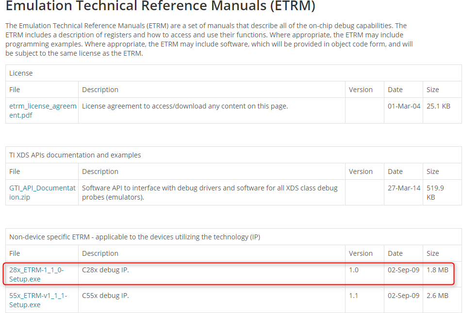
    after almost 3 years we've a new request for device in object. Now I've accesso to  Emulation Developer Community Extranet and I want to download the related ETRM. But I need to know which is the Debug port name and version mounted on TMS320F28335 device (OMAP, IcePick or whatever). There's a list of ETRM but I can't find which is the right one.

    Regards,

  • Samuele,

    It is the one called 28x_ETM-1_1_0-Setup.exe

    Regards,

    John

  • Dear JohnS,

    thanks for your answer, I downloaded the file you mentioned above and I have a couple of questions:

    1) Inside the document I found a bunch of register which are able to program the MU. (SYS_ACC MU and many others) Is MU definition including flash memory? Or does it include only RAM?

    2) Do I have to consider some kind of initializations before accessing these registers? I mean both hardware (TRST of JTRST lines on power up) or some init on CPU (halting the core for example)

    Thank you very much,

  • 1) MU is only for the direct memory bus.  That would include reading values from flash, but to write to flash would require additional steps (e.g. erasing a sector, putting the flash into a programming mode, etc) that would depend on the nature of the flash being used.

    2) The registers would not be accessible until the target is in debug mode.  To do that, perform the following steps:

    - Put the target into Test-Logic-Reset (either pull TRST low, or hold TMS high while toggling TCK for at least 7 cycles)

    - Execute an IR path scan to write a value of 0x000000aa into DC_STRBS

  • Edward Fewell said:
    to write to flash would require additional steps (e.g. erasing a sector, putting the flash into a programming mode, etc) that would depend on the nature of the flash being used.

    Following on to the information provided by Edward.  Programming of flash on 28x devices is always done by the CPU executing a flash programming algorithm. TI calls this the flash API. Any communications port with a host could be used; for example SCI, CAN, USB, or in your case JTAG. 


    The JTAG commands would be used to download a little application to the device.  This application would understand what the host is asking to be done (ex: a buffer of data to program, or erase a sector) and would make calls into the API and communicate back to the API.  (In this case JTAG commands might be used to stop at a breakpoint and then read pass/fail data from RAM).


    This concept,  using SCI as an example comm port, is described in this application note:

    http://www.ti.com/lit/sprabv4

    Regards,

    Lori

  • Hi Edward and Lori,

    thank you very much for your precious support. That's the information I needed. As you explained that a flashing firmware running on RAM is still necessary, I ask you also what instruction can be used to point the PC to the first firmware instruction and if i need to stop  the CPU before downloading it.

    Thanks, 

  • In general, it would work like this:

    1) Do a debug connection and halt the CPU.

    2) Write the flash application to RAM.

    3) Write data to be flashed into RAM.

    4) Put the PC to the entry point of the flash application.

    5) Run the CPU.

    6) Watch to see if the application has complete (either read the PC or whether the CPU halted or read a flag in RAM, depends on how the application intends to signal completion).

    7) Repeat 3 through 6 until all of the data has been written.