This thread has been locked.

If you have a related question, please click the "Ask a related question" button in the top right corner. The newly created question will be automatically linked to this question.

DLP3310: optic setup

Part Number: DLP3310

Hi there,

I sketched up a simplified optic system for pico projector using DLP3310 based on 17 degree rotation. I add a reflective mirror which is not mentioned in DLP3310 spec. It seems the rotation of the mirror is along diagonal axis, tilt 12 degree then rotate 12 degree. A little bit confused. Wondering the ultimate direction the mirror is facing. Can you please advise the feasibility of the configuration and provide more detail  
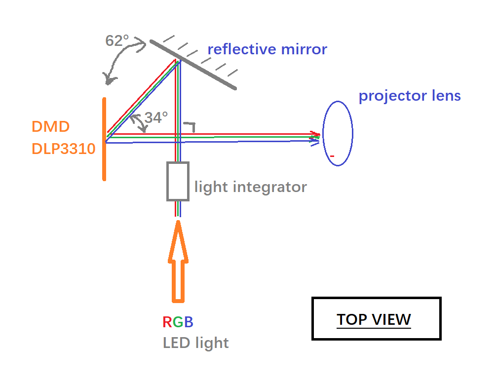
regarding to light path, angle etc. Any drawings or sketches from top view. would be much appreciated. Thanks.

kind regards

Frank

  • Hello Frank,

    Could you clarify if you are trying to design your own optical system for the DLP3310 DMD or are you trying to understand our existing optical engine design on the DLP3310EVM?

    Thanks,
    Kyle
  • Hi Kyle,

    I am designing my own pico projector including optic system based on DLP3310 DMD. I do not quite understand the actual face direction of mirror for each state, on/off/flat (12 degree? 17 degree? or something else).

    I need understand the angle between on/off state related to flat face (presumed paralleled with projection lens main plane) , any rotation along the normal of mirror face, and light path such that I could figure out the optic configuration.  The attached design is what I understand and am planning to design. Can you please advise the information? thanks.

    kind regards

    frank

  • Hello Frank,

    I hope this image helps.

    Thanks,

    Kyle

  • Hi Kyle,

    The axis does explain a lot. Thanks for your help.

    Cheers

    Frank

  • Hi Kyle,

    Just realize the micromirror tilt image you post for on-state is rotating count-clockwise along vertical axis. While the light coming through from left side which looks the light is going to shot the rear side of individual mirror. Can you please explain a little bit about this?

    Another question is about voltage selection guideline for the system. As it is a quite wide range for voltage(min to max) for Voffset, Vbias, Vreset, |Vbias-Voffset|, |Vbias-Vreset|, is there any guideline to select the most proper value for these voltages. My system nominal voltage/battery is set to 12V. Can you provide any suggestion, please?

    Third question is, can DLP3310 by soldered on PCB (page 33 on DLP3310 spec says 'connect to PCB') or other mounting method? Thanks

    Kind regards

    Frank

  • Hi Frank,

    For your first query, please see this thread for the movement of TRP pixel and you can realize at on state the illumination is on DMD and in OFF state the illumination is on rear side of mirror. : e2e.ti.com/.../734578

    For second query, you can use Vbias :18V, Voffset: 10V, Vreset : -14V

    For third query, No DLP3310 is not soldered on PCB, it place on the PCB using an interposer.

    Thanks,
    Navneet