This thread has been locked.

If you have a related question, please click the "Ask a related question" button in the top right corner. The newly created question will be automatically linked to this question.

some experiments and problems

I did some experiments with LCR and meat with some questions.

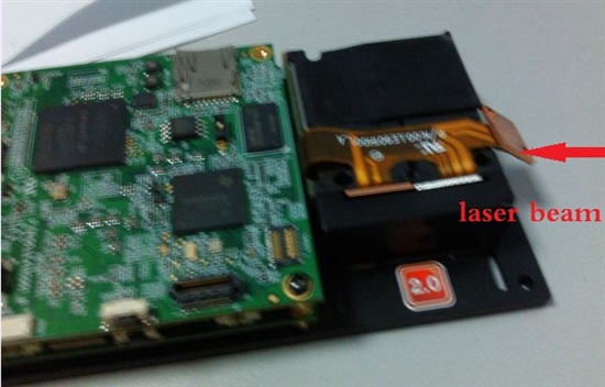
1.I  remove  the entire light engine,and illuminate the DMD with laser  beam(showed  below pic). 

I choose internal test pattern, "Fine Checker Board" . The pattern DMD projects is like this

Every  small speckle in the picture is just "Fine Checker Board", but it  repeats  spatially and periodically, as showed above picture. 

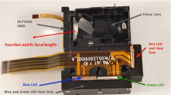
Here comes my question. Why the small "Fine Checker Board" pattern  repeats spatially? Because there is only one DMD array ,and thus there should be only one spot. I am wondering  if it is caused by the mirror covering over the DMD array. If it is for this reason, what's the function of the Plano-convex Spherical lenses next to DMD? With this lens ,the mentioned repetition disappears. By the way, do anybody know the focal length of the lens?

 (via 

2. I remove red LED light source only,and relpace it with a laser one(blue and green  LED  unlighted ) .Showed below.

It works well .As with  LED source, the picture it shows is just the picture loaded . The only difference is the laser projected picture shows small spots arranged neatly , both horizontally and vertically. I guess it is the fly-eye lens. But Why LED picture shows no such spots?

3. The images LCR projects change size with distance.I am attempting to collimate the beam (I hope the image it projects does not change size with distance), do anyone have experiences ?


Thanks

Jin

  • Jin,

    What you have discovered is the diffraction effects of a regular array of mirrors. This is perfectly normal, and is a result of using a coherent light source.

    If you remove the projection optics and illuminate the DMD directly with an LED or other non-coherent light source, you will not notice this effect. Instead you will see that the light is scattered, but not imaged. With the coherent light, you will see many repetitions - or diffraction orders - reproducing the image on the DMD.

    This effect can be used to advantage in certain lensless imaging applications, but is usually used with Fourier encoded data on the DMD which results in recognizable patterns, or pictures, in the diffracted orders.

  • Pascal,

    From your explanation, it's not suitable to illuminate a DMD directly with a coherent source in order to produce a pattern.,right?

    What's the function of the lens close to DMD array? Because when I replace red LED with a laser source (below), I do get a  image just as  using LED light. The only difference is that the former  shows small spots arranged neatly besides the image.


    Do you have any idea about how to shorten the focus length of  projection optics? For I just want a pattern with small size ,which I think can be achieved by changing its  

    focus length. 

    The wavelength of the red LED of LCR's light engine is 617nm. Is there LED with higher wavelength, such as 780nm or higher ?

    Thank you!

  • Jin,

    It is possible to illuminate a DMD with laser (coherent light), but you will observe diffraction effects which are there, but not as visible, with broad-band (LED) illumination. It is the physics of light.

    I can't answer specific questions about the internals of the light engine. The light engine is designed and manufactured by Young Optics (Taiwan) - but we don't have detailed design notes.

    I answered your question about the throw ratio - projected image size - in the other thread which you posted to.

    There are LEDs of many different wavelengths available.  I can not say which ones (if any) are drop-in replacements for the LightCrafter light engine. The LEDs in the LightCrafter light engine are part of the Young Optics design, and is not in the posted BOM.

  • Hello All,

    We use The lightcrafter with lasers (coherent light source) and have solved the problem of diffraction by re-imaging the DMD onto our detectors. You could use a screen to visualize the re-imaged DMD. This is done by collecting all the diffraction orders(spots) using an imaging lens. you should see that all the diffraction orders merge back into one spot.

    Bharat