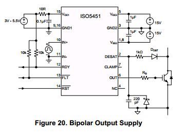
Hello, I have some questions about designning with ISO5451,would you please help me?
I am just using ISO5451 to driving my IGBT. the collector voltage of IGBT is about 320V and bipolar output supply(+15V and -9V).
and the schematic is the same as figure 20 in the ISO 5451 datasheet.
I have 3 questions about the usage:
1, what is the right boot sequence, the Vcc1,Vcc2 and Vee2 boot first or the collector voltage first?why?
2, shall I pull the /RST low through the boot process? The /RST pin has a internal pull high resistor,but I found that I must pull low the /RST unless the IGBT collector voltage had raised,or if /RST has been high before the IGBT collector voltage raised,there will be about 100V pulse on Vcc2(+15v),when the collector voltage rising.
3,when use the bipolar output supply,how to deal with the CLAMP pin,left it open,or connect to GND1,GND2?


