This thread has been locked.

If you have a related question, please click the "Ask a related question" button in the top right corner. The newly created question will be automatically linked to this question.

Idea about upgrade firmware for C2000

Hi,

I've already used API library for read/write emulation eeprom. So, I think i can use this method to upgrade firmware for my MCU(28335). My idea is: Bootloader program store in flashA and flashD (run in RAML0) , application program store in flashE and flashF(run in RAML1). This is my flow-chart
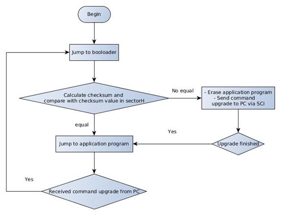
After received data, and write to flash, i will calculate checksum and store this value in flashH.

If you've already written a custom bootloader, you think my idea can be possible. And how can i jump from program in bootloader to application program.

Thanks. 

  • Hi,

    I found  a piece of program that jump to a sector 

     .text
    _jumpToApplicationEntry:
      SETC INTM;
      ZAPA;
      MOV @SP,#0;
      PUSH ACC; 
      PUSH AL;
      MOV AL, #0x0a08;
      PUSH AL;
      MOVL XAR7, #0x300000;     SectorH
      PUSH XAR7;
      POP RPC;
      POP ST1;
      POP ST0;
      POP IER;
      POP DBGIER;
      LRETR;  

    Is it right ? And i put it in .cmd or .c 

    Thanks for helping me

  • Phien,

    To jump from one program to another, you should use a hard address.  This is how the TI ROM bootloader jump to the flash entry point for your program.

    Here's what I mean.  Suppose you have Program A, and you want to jump to Program B.  Choose a hard address in the Program B flash.  Typically, this might be the last two words in the flash used by B.  You need two words because you put a long branch (LB) instruction there.  In all the TI examples, there is a file called CodeStartBranch.asm.  This contains a section called 'codestart' that contains nothing but a LB instruction.  The LB points to the start of the program (typically _c_int00, or a Watchdog Disable function).  The linker .cmd file is used to stick the 'codestart' section to the two words of flash at the hard address.  Then in Program A, all you have to do is branch to that hard address, e.g.,

    asm(" LB 0x317FFE");

    The above is an inline assembly statement that you can embed in your C program.  I've done this in straight C also but don't recall off the top of my head how the syntax looks.

    Regards,

    David

  • Hi David,

    If in the first program, i use flash api, the second program i use FPUfastRTC. If i load .out file of project #1 then i only copy program memory store in flash that i used in second program. You think the second program can run as i need.

    Thanks. 

  • I see in .cmd:

    BEGIN       : origin = 0x33FFF6, length = 0x000002
    codestart           : > BEGIN       PAGE = 0
    

    So if first program i flash A, i use this configuration, but if second program i use flash B , can i use this configuration.

    And if in my program use 2 flash sectors, such as B and C. so what hardware address i use in LB.

    Thanks so much

  • Phien,

    Phien Nguyen said:

    If in the first program, i use flash api, the second program i use FPUfastRTC. If i load .out file of project #1 then i only copy program memory store in flash that i used in second program. You think the second program can run as i need.

    The two programs are completely independent CCS projects.  Each will contain whatever libraries and source files it needs.  There could even be the same library in each (e.g., compiler RTS library) meaning you have two copies of this library in flash.  That is OK.  Again, each program should be completely indepedent.  Your bootloader simply transfers control to your main application project when the time comes.

    Phien Nguyen said:

    I see in .cmd:

    BEGIN       : origin = 0x33FFF6, length = 0x000002
    codestart           : > BEGIN       PAGE = 0
    

    So if first program i flash A, i use this configuration, but if second program i use flash B , can i use this configuration.

    And if in my program use 2 flash sectors, such as B and C. so what hardware address i use in LB.

     
    You are on the right track.  Your bootloader program will have BEGIN linked as shown above.  That way, the ROM bootloader will transfer control to your bootloader prorgam after a reset.
     
    For your main application project, you will have a completely seperate linker .cmd file.  You should locate BEGIN at a flash address that is being used by your main application.  For example, if the main application resides in flash sectors B and C, you might use the last two words in B (i.e., the highest two addresses) to hold BEGIN.  That keeps the BEGIN section nicely out of the way at the end of the flash being used.  Your bootloader would then do a LB (branch) to the address where the BEGIN section of the main application is.
     
    Regards,
    David
  • Thank you so much David.

  •  i use asm("LB 0X330000") in the C file.

    Follwoing is c file.


    while(1) {
    if(mode_selection == image_upload_mode)

    {

    switch(Decode_cmd)
    {   

     case MSG_ID_UPLOAD_READY:

    {

    DELAY_US(500000);
    Decode_cmd = 0;
    ack_plus(0x87);
    break;
    }


    case MSG_ID_UPLOADING:
    {
    if(finished_storing_image_in_fpga == 0)
    {
    write_512byte_to_flash();
    }

    else
    { Program_IMG_flash(); Decode_cmd = 0;
    } DELAY_US(500000); break; }
    default: { break; } }
    } else if(mode_selection == mission_mode) {
    asm("LB 0x330000"); }


    GpioDataRegs.GPADAT.bit.GPIO29 = 0; GpioDataRegs.GPBDAT.bit.GPIO32 = 0;
    DELAY_US(0100000); GpioDataRegs.GPADAT.bit.GPIO29 = 1;
    GpioDataRegs.GPBDAT.bit.GPIO32 = 1; DELAY_US(0100000);


    but i see the error message.
    "C:/ti/ccsv5/tools/compiler/c2000_6.2.0/bin/cl2000" -v28 -ml -mt --float_support=fpu32 --include_path="C:/ti/ccsv5/tools/compiler/c2000_6.2.0/include" --include_path="D:/dsp_workspace/f2/F2_UPLOAD_VER2/header" -g --diag_warning=225 --display_error_number --diag_wrap=off --preproc_with_compile --preproc_dependency="MAIN.pp" "../MAIN.c"
    "C:\Users\70805\AppData\Local\Temp\0708010", ERROR! at line 444: [E0002] Invalid mnemonic specification

    LB 0x330000

    why?please help me to solve the problem

    is there anything to use asm("LB 0x330000") in a c file?

  • You need a space after the leading quotation mark in inline assembly:

    asm(" LB 0x330000");

    Regards,
    David
  • Hi Thank you for your help.
    I solve the problem related asm(" LB 0x330000"); thank to you.
    But after execute asm(" LB 0x330000");
    interrupt void ILLEGAL_ISR(void) // Illegal operation TRAP{
    // Insert ISR Code here
    // Next two lines for debug only to halt the processor here
    // Remove after inserting ISR Code asm(" ESTOP0"); for(;;);}
    Ccs stop in the above ISR in the DSP2833X_Defaultisr.c file.
    I don’t know why my upload project stopped in the ISR.Please help me.
    Following is the file including asm(" LB 0x330000").switch(Decode_cmd)
    {
    case MSG_ID_UPLOAD_READY:
    {
    DELAY_US(500000);
    Decode_cmd = 0;
    ack_plus(0x87);
    break;
    }
    case MSG_ID_UPLOADING:
    {
    if(finished_storing_image_in_fpga == 0)
    {
    write_512byte_to_flash();
    }
    else
    {
    Program_IMG_flash();
    Decode_cmd = 0;
    }
    DELAY_US(400000);
    break;
    }
    case mission_mode:
    {
    Decode_cmd = 0;
    asm(" LB 0x330000");
    break;
    }
  • And following is my linker.cmd
    Following linker command file is used by upload.prj and application.prj in common.
    Upload.prj is project which receive hex image. And write hex image to FLASH SECTOR C.
    Application.prj is using SECTOR C .
    Difference between upload.prj and application.prj command file each is flash sector.
    upload.prj is using sector Aapplication.prj is using sector C instead of A.
    Following is upload command file MEMORY{PAGE 0: /* Program Memory */
    /* Memory (RAM/FLASH/OTP) blocks can be moved to PAGE1 for data allocation */
    ZONE0 : origin = 0x004000, length = 0x001000 /* XINTF zone 0 */
    RAML0 : origin = 0x008000, length = 0x001000 /* on-chip RAM block L0 */
    RAML1 : origin = 0x009000, length = 0x001000 /* on-chip RAM block L1 */
    RAML2 : origin = 0x00A000, length = 0x001000 /* on-chip RAM block L2 */
    RAML3 : origin = 0x00B000, length = 0x001000 /* on-chip RAM block L3 */
    ZONE6 : origin = 0x0100000, length = 0x100000 /* XINTF zone 6 */
    ZONE7A : origin = 0x0200000, length = 0x010000 /* XINTF zone 7 - program space */
    FLASHH : origin = 0x300000, length = 0x008000 /* on-chip FLASH */
    FLASHG : origin = 0x308000, length = 0x008000 /* on-chip FLASH */
    FLASHF : origin = 0x310000, length = 0x008000 /* on-chip FLASH */
    FLASHE : origin = 0x318000, length = 0x008000 /* on-chip FLASH */
    FLASHD : origin = 0x320000, length = 0x008000 /* on-chip FLASH */
    FLASHC : origin = 0x328000, length = 0x008000 /* on-chip FLASH */
    FLASHA : origin = 0x338000, length = 0x007F80 /* on-chip FLASH */
    CSM_RSVD : origin = 0x33FF80, length = 0x000076 /* Part of FLASHA. Program with all 0x0000 when CSM is in use. */
    BEGIN : origin = 0x33FFF6, length = 0x000002 /* Part of FLASHA. Used for "boot to Flash" bootloader mode. */
    CSM_PWL : origin = 0x33FFF8, length = 0x000008 /* Part of FLASHA. CSM password locations in FLASHA */
    OTP : origin = 0x380400, length = 0x000400 /* on-chip OTP */
    ADC_CAL : origin = 0x380080, length = 0x000009 /* ADC_cal function in Reserved memory */

    IQTABLES : origin = 0x3FE000, length = 0x000b50 /* IQ Math Tables in Boot ROM */
    IQTABLES2 : origin = 0x3FEB50, length = 0x00008c /* IQ Math Tables in Boot ROM */
    FPUTABLES : origin = 0x3FEBDC, length = 0x0006A0 /* FPU Tables in Boot ROM */
    ROM : origin = 0x3FF27C, length = 0x000D44 /* Boot ROM */
    RESET : origin = 0x3FFFC0, length = 0x000002 /* part of boot ROM */
    VECTORS : origin = 0x3FFFC2, length = 0x00003E /* part of boot ROM */
    PAGE 1 : /* Data Memory */
    /* Memory (RAM/FLASH/OTP) blocks can be moved to PAGE0 for program allocation */
    /* Registers remain on PAGE1 */

    BOOT_RSVD : origin = 0x000000, length = 0x000050 /* Part of M0, BOOT rom will use this for stack */
    RAMM0 : origin = 0x000050, length = 0x0003B0 /* on-chip RAM block M0 */
    RAMM1 : origin = 0x000400, length = 0x000400 /* on-chip RAM block M1 */
    RAML4 : origin = 0x00C000, length = 0x001000 /* on-chip RAM block L1 */
    RAML5 : origin = 0x00D000, length = 0x001000 /* on-chip RAM block L1 */
    RAML6 : origin = 0x00E000, length = 0x001000 /* on-chip RAM block L1 */
    RAML7 : origin = 0x00F000, length = 0x001000 /* on-chip RAM block L1 */
    // ZONE7B : origin = 0x20FC00, length = 0x000400 /* XINTF zone 7 - data space */
    FLASHB : origin = 0x330000, length = 0x008000 /* on-chip FLASH */
    DEV_EMU : origin = 0x000880, length = 0x000180 /* device emulation registers */
    FLASH_REGS : origin = 0x000A80, length = 0x000060 /* FLASH registers */
    CSM : origin = 0x000AE0, length = 0x000010 /* code security module registers */

    ADC_MIRROR : origin = 0x000B00, length = 0x000010 /* ADC Results register mirror */

    XINTF : origin = 0x000B20, length = 0x000020 /* external interface registers */

    CPU_TIMER0 : origin = 0x000C00, length = 0x000008 /* CPU Timer0 registers */
    CPU_TIMER1 : origin = 0x000C08, length = 0x000008 /* CPU Timer0 registers (CPU Timer1 & Timer2 reserved TI use)*/
    CPU_TIMER2 : origin = 0x000C10, length = 0x000008 /* CPU Timer0 registers (CPU Timer1 & Timer2 reserved TI use)*/

    PIE_CTRL : origin = 0x000CE0, length = 0x000020 /* PIE control registers */
    PIE_VECT : origin = 0x000D00, length = 0x000100 /* PIE Vector Table */
    DMA : origin = 0x001000, length = 0x000200 /* DMA registers */
    MCBSPA : origin = 0x005000, length = 0x000040 /* McBSP-A registers */
    MCBSPB : origin = 0x005040, length = 0x000040 /* McBSP-B registers */

    ECANA : origin = 0x006000, length = 0x000040 /* eCAN-A control and status registers */
    ECANA_LAM : origin = 0x006040, length = 0x000040 /* eCAN-A local acceptance masks */
    ECANA_MOTS : origin = 0x006080, length = 0x000040 /* eCAN-A message object time stamps */
    ECANA_MOTO : origin = 0x0060C0, length = 0x000040 /* eCAN-A object time-out registers */
    ECANA_MBOX : origin = 0x006100, length = 0x000100 /* eCAN-A mailboxes */

    ECANB : origin = 0x006200, length = 0x000040 /* eCAN-B control and status registers */
    ECANB_LAM : origin = 0x006240, length = 0x000040 /* eCAN-B local acceptance masks */
    ECANB_MOTS : origin = 0x006280, length = 0x000040 /* eCAN-B message object time stamps */
    ECANB_MOTO : origin = 0x0062C0, length = 0x000040 /* eCAN-B object time-out registers */
    ECANB_MBOX : origin = 0x006300, length = 0x000100 /* eCAN-B mailboxes */

    EPWM1 : origin = 0x006800, length = 0x000022 /* Enhanced PWM 1 registers */
    EPWM2 : origin = 0x006840, length = 0x000022 /* Enhanced PWM 2 registers */
    EPWM3 : origin = 0x006880, length = 0x000022 /* Enhanced PWM 3 registers */
    EPWM4 : origin = 0x0068C0, length = 0x000022 /* Enhanced PWM 4 registers */
    EPWM5 : origin = 0x006900, length = 0x000022 /* Enhanced PWM 5 registers */
    EPWM6 : origin = 0x006940, length = 0x000022 /* Enhanced PWM 6 registers */

    ECAP1 : origin = 0x006A00, length = 0x000020 /* Enhanced Capture 1 registers */
    ECAP2 : origin = 0x006A20, length = 0x000020 /* Enhanced Capture 2 registers */
    ECAP3 : origin = 0x006A40, length = 0x000020 /* Enhanced Capture 3 registers */
    ECAP4 : origin = 0x006A60, length = 0x000020 /* Enhanced Capture 4 registers */
    ECAP5 : origin = 0x006A80, length = 0x000020 /* Enhanced Capture 5 registers */
    ECAP6 : origin = 0x006AA0, length = 0x000020 /* Enhanced Capture 6 registers */

    EQEP1 : origin = 0x006B00, length = 0x000040 /* Enhanced QEP 1 registers */
    EQEP2 : origin = 0x006B40, length = 0x000040 /* Enhanced QEP 2 registers */

    GPIOCTRL : origin = 0x006F80, length = 0x000040 /* GPIO control registers */
    GPIODAT : origin = 0x006FC0, length = 0x000020 /* GPIO data registers */
    GPIOINT : origin = 0x006FE0, length = 0x000020 /* GPIO interrupt/LPM registers */

    SYSTEM : origin = 0x007010, length = 0x000020 /* System control registers */
    SPIA : origin = 0x007040, length = 0x000010 /* SPI-A registers */
    SCIA : origin = 0x007050, length = 0x000010 /* SCI-A registers */
    XINTRUPT : origin = 0x007070, length = 0x000010 /* external interrupt registers */
    ADC : origin = 0x007100, length = 0x000020 /* ADC registers */
    SCIB : origin = 0x007750, length = 0x000010 /* SCI-B registers */
    SCIC : origin = 0x007770, length = 0x000010 /* SCI-C registers */
    I2CA : origin = 0x007900, length = 0x000040 /* I2C-A registers */
    CSM_PWL : origin = 0x33FFF8, length = 0x000008 /* Part of FLASHA. CSM password locations. */

    PARTID : origin = 0x380090, length = 0x000001 /* Part ID register location */
    } /* Allocate sections to memory blocks. Note:
    codestart user defined section in DSP28_CodeStartBranch.asm used to redirect code
    execution when booting to flash
    ramfuncs user defined section to store functions that will be copied from Flash into RAM
    */ SECTIONS{ PieVectTableFile : > PIE_VECT, PAGE = 1
    /*** Peripheral Frame 0 Register Structures ***/
    DevEmuRegsFile : > DEV_EMU, PAGE = 1
    FlashRegsFile : > FLASH_REGS, PAGE = 1
    CsmRegsFile : > CSM, PAGE = 1
    AdcMirrorFile : > ADC_MIRROR, PAGE = 1
    XintfRegsFile : > XINTF, PAGE = 1
    CpuTimer0RegsFile : > CPU_TIMER0, PAGE = 1
    CpuTimer1RegsFile : > CPU_TIMER1, PAGE = 1
    CpuTimer2RegsFile : > CPU_TIMER2, PAGE = 1
    PieCtrlRegsFile : > PIE_CTRL, PAGE = 1
    DmaRegsFile : > DMA, PAGE = 1
    /*** Peripheral Frame 3 Register Structures ***/
    McbspaRegsFile : > MCBSPA, PAGE = 1
    McbspbRegsFile : > MCBSPB, PAGE = 1
    /*** Peripheral Frame 1 Register Structures ***/
    ECanaRegsFile : > ECANA, PAGE = 1
    ECanaLAMRegsFile : > ECANA_LAM PAGE = 1
    ECanaMboxesFile : > ECANA_MBOX PAGE = 1
    ECanaMOTSRegsFile : > ECANA_MOTS PAGE = 1
    ECanaMOTORegsFile : > ECANA_MOTO PAGE = 1
    ECanbRegsFile : > ECANB, PAGE = 1
    ECanbLAMRegsFile : > ECANB_LAM PAGE = 1
    ECanbMboxesFile : > ECANB_MBOX PAGE = 1
    ECanbMOTSRegsFile : > ECANB_MOTS PAGE = 1
    ECanbMOTORegsFile : > ECANB_MOTO PAGE = 1
    EPwm1RegsFile : > EPWM1 PAGE = 1
    EPwm2RegsFile : > EPWM2 PAGE = 1
    EPwm3RegsFile : > EPWM3 PAGE = 1
    EPwm4RegsFile : > EPWM4 PAGE = 1
    EPwm5RegsFile : > EPWM5 PAGE = 1
    EPwm6RegsFile : > EPWM6 PAGE = 1
    ECap1RegsFile : > ECAP1 PAGE = 1
    ECap2RegsFile : > ECAP2 PAGE = 1
    ECap3RegsFile : > ECAP3 PAGE = 1
    ECap4RegsFile : > ECAP4 PAGE = 1
    ECap5RegsFile : > ECAP5 PAGE = 1
    ECap6RegsFile : > ECAP6 PAGE = 1
    EQep1RegsFile : > EQEP1 PAGE = 1
    EQep2RegsFile : > EQEP2 PAGE = 1
    GpioCtrlRegsFile : > GPIOCTRL PAGE = 1
    GpioDataRegsFile : > GPIODAT PAGE = 1
    GpioIntRegsFile : > GPIOINT PAGE = 1
    /*** Peripheral Frame 2 Register Structures ***/
    SysCtrlRegsFile : > SYSTEM, PAGE = 1
    SpiaRegsFile : > SPIA, PAGE = 1
    SciaRegsFile : > SCIA, PAGE = 1
    XIntruptRegsFile : > XINTRUPT, PAGE = 1
    AdcRegsFile : > ADC, PAGE = 1
    ScibRegsFile : > SCIB, PAGE = 1
    ScicRegsFile : > SCIC, PAGE = 1
    I2caRegsFile : > I2CA, PAGE = 1
    /*** Code Security Module Register Structures ***/
    CsmPwlFile : > CSM_PWL, PAGE = 1
    /*** Device Part ID Register Structures ***/
    PartIdRegsFile : > PARTID, PAGE = 1
    /* Allocate program areas: */
    .cinit : > FLASHA PAGE = 0//NOLOAD SECTION, used to initailize c Global varalbles at startup, initialized section
    .pinit : > FLASHA, PAGE = 0//global constructors for c++program.
    .text : > FLASHA PAGE = 0//Program code, initialized section
    codestart : > BEGIN PAGE = 0
    ramfuncs : LOAD = FLASHA, RUN = RAML0,
    LOAD_START(_RamfuncsLoadStart),
    LOAD_END(_RamfuncsLoadEnd),
    RUN_START(_RamfuncsRunStart),
    PAGE = 0
    csmpasswds : > CSM_PWL PAGE = 0
    csm_rsvd : > CSM_RSVD PAGE = 0
    /* Allocate uninitalized data sections: */// uninitailized section is not load. allocate only once for uninitialized section for run address. ignore load address
    .stack : > RAMM1 PAGE = 1
    .ebss : > RAML4 PAGE = 1
    .esysmem : > RAMM1 PAGE = 1
    /* Initalized sections go in Flash */
    /* For SDFlash to program these, they must be allocated to page 0 */
    .econst : > FLASHA PAGE = 0
    .switch : > FLASHA PAGE = 0
    /* Allocate IQ math areas: */
    IQmath : > FLASHA PAGE = 0 /* Math Code */
    IQmathTables : > IQTABLES, PAGE = 0, TYPE = NOLOAD
    /* Uncomment the section below if calling the IQNexp() or IQexp()
    functions from the IQMath.lib library in order to utilize the
    relevant IQ Math table in Boot ROM (This saves space and Boot ROM
    is 1 wait-state). If this section is not uncommented, IQmathTables2
    will be loaded into other memory (SARAM, Flash, etc.) and will take
    up space, but 0 wait-state is possible. */ /*
    IQmathTables2 : > IQTABLES2, PAGE = 0, TYPE = NOLOAD {
    IQmath.lib<IQNexpTable.obj> (IQmathTablesRam) } */
    FPUmathTables : > FPUTABLES, PAGE = 0, TYPE = NOLOAD
    /* Allocate DMA-accessible RAM sections: */
    DMARAML4 : > RAML4, PAGE = 1
    DMARAML5 : > RAML5, PAGE = 1
    DMARAML6 : > RAML6, PAGE = 1
    DMARAML7 : > RAML7, PAGE = 1
    /* Allocate 0x400 of XINTF Zone 7 to storing data */
    ZONE7DATA : > ZONE7A, PAGE = 0
    /* .reset is a standard section used by the compiler. It contains the */
    /* the address of the start of _c_int00 for C Code. /*
    /* When using the boot ROM this section and the CPU vector */
    /* table is not needed. Thus the default type is set here to */
    /* DSECT */ .reset : > RESET, PAGE = 0, TYPE = DSECT
    vectors : > VECTORS PAGE = 0, TYPE = DSECT
    /* Allocate ADC_cal function (pre-programmed by factory into TI reserved memory) */
    .adc_cal : load = ADC_CAL, PAGE = 0, TYPE = NOLOAD Flash28_API:
    { -lFlash28335_API_V210.lib(.econst)
    -lFlash28335_API_V210.lib(.text)
    } LOAD = FLASHA,
    RUN = RAML0|RAML1|RAML2|RAML3,
    LOAD_START(_Flash28_API_LoadStart),
    LOAD_END(_Flash28_API_LoadEnd),
    RUN_START(_Flash28_API_RunStart),
    PAGE = 0 }
  • HiI solved the problem thank to you.I did it as you say in the power point.
    At first it didn’t work.So I have following 2 entry point to be the same.
    First is following hex.cmd
    Following entry point is "_c_int00" address: 00338976 in the map file


    ** =============== hex.cmd ====================***/
    UPLOAD.out /* input COFF file */
    --map UPLOAD.map /* create a hex map file */
    -a /* create ASCII image */
    --image /* Create a memory image (no discontinuities) */
    --order=LS /* little endian */
    --zero /* reset address origin to 0 for output file(s) */
    --memwidth 16
    --boot /* create a boot table for all initialized sects */
    --entrypoint=0x0032898dROMS{
    wonseok: org = 0x328000, len = 0x2000, romwidth = 16, files = {.\upload_final.hex}, fill = 0xffff
    }

    Following is the map fileOUTPUT FILE NAME: <UPLOAD.out>
    ENTRY POINT SYMBOL: "_c_int00" address: 00338976

    Second is upload.prj
    asm(" LB 0x0032898d");//entry pointfollowing is the main.c in the upload.prj
    while(1) {
    switch(Decode_cmd)
    {
    case MSG_ID_UPLOAD_READY:
    {
    DELAY_US(500000);
    Decode_cmd = 0;
    ack_plus(0x87);
    break;
    }
    case MSG_ID_UPLOADING:
    {
    if(finished_storing_image_in_fpga == 0)
    {
    write_512byte_to_flash();
    }
    else
    {
    Program_IMG_flash();
    Decode_cmd = 0;
    }
    DELAY_US(400000);
    break;
    }
    case mission_mode:
    {
    Decode_cmd = 0;
    asm(" LB 0x0032898d");//entry point
    break;
    }


    Then it work that I intend.But problem is occurred.
    Whenever main.prj code is modified, entry point will be changed because of code size.
    So how can upload.prj know the changing entry point address?
    I want to fix entry point.Is it possible to fix entry point from the .map file?
    If it is impossible, I want have upload.prj receive the changed entry point. And asm(" LB changing");//entry point
    Do I make code in assembly?Please helpThank you for your help.

  • hiDavid.i am so unhappy. i have not solved yet.is it possible that i call you?
    i want to call about 28335 problem.
    please send me your phone numer through e-mail.my e-mail choiwonseok@lignex1.com
  • HI DAVID.I am planning to seperate project to two project.
    First is application project. and in the flash sector A
    second is upload project. and in the flash sector C.
    But when i get hex image file of upload project, i can't find codestart address in the .hex file.
    but i can check codestart address in the follwoing map file.


    OUTPUT FILES: .\upload_final.hex [b0..b15]
    CONTENTS: 00328000..00329251 BOOT TABLE
    .cinit : dest=00329134 size=0000007b width=00000002
    .text : dest=00328000 size=00000ab4 width=00000002
    codestart : dest=0032be01 size=00000002 width=00000002
    ramfuncs : dest=00328ab4 size=0000001f width=00000002
    csmpasswds : dest=0033fff8 size=00000008 width=00000002
    csm_rsvd : dest=0033ff80 size=00000076 width=00000002
    .econst : dest=00329034 size=00000100 width=00000002
    Flash28_API : dest=00328ad4 size=00000560 width=00000002
    00329252..0032bfff FILL = 0000ffff


    but after execute hex2000, I can only see the FFFF at the 0x32be01.why?help me

  • it it possible send me your e-mail address.
    it's very difficult to upload big size file on this E2E service because of our company security policy