This thread has been locked.

If you have a related question, please click the "Ask a related question" button in the top right corner. The newly created question will be automatically linked to this question.

TMS320F28335, EPWM switches Off after Motorinitialization

Hallo,

we use 28335 for ec-motor control. We are in production since 13 month, and have a problem with about 5% units.

Diagnose:

We use the High-resolution PWM'S for a 3-phase ec-motor with FOC control. All is working well.

After several turns with fixed motor current to detect encoder reference, we use fix vectors to detect the magnet system and switch then

in the "normal" FOC mode. At this time at 5% of the PCB's with 28335 the EPWM outputs were set to zero. This occurs only if the PCB has operating temperature of about 30-35 degrees. When we cool the PCB area under the 28335, switch on and off, the error disappears.

When I contact the 28335 with the JTAG debugger (Blackhawk) I can also restart the system correct and the EPMW output are in normal state when starting the FOC (duty cycle 50%).

When switching the motorcontrol from magnet detection mode to FOC mode, the EPWM outputs or any 28335 register will not be touched.

We have examined the solder point of the 28335 BGA with X-Ray technology, no result.

My question:

Is there any simular bug known?

Is there a 28335 PIN which can possibly cause this (e.G. a jtag pin)?

would be nice to here from anybody!

  • Hello Ralf,

    I have not seen this or heard of this behavior with the 28335 device.

    Is it possible to reproduce this failure with the debugger connected? If yes, check whether the trip zone flags (TZFLG) are Set after the failure occurs. Are you using the trip zone sub-module of the PWMs to implement fault protection? Is it possible that some noise is coupling in and causing a spurious trip? The TZ inputs are active low digital inputs. Do you have an external pull-up on these inputs? Is there a TZ input pin used by the code but left open on the board? Do you have a temperature sensor based PWM trip function?

    Finally, when you say you use high resolution PWMs are you using the HRPWM feature of the ePWM modules? The HRPWM feature allows users to control the PWM outputs with high resolution.

    Hopefully answers to above questions will help us debug this issue.

    Hrishi 

  • Hallo Hrishi,

    thanks for your reply.

    Yes we can start it always with the debugger connected, we use the USB2000 from BH!

    Your thoughts about the trip zone will be checked soon.

    br Ralf

  • Hallo Hrishi,

    it seems to be a miracle. I've made several steps to detect the error when it appears.

    As I wrote yesterday, it always works when I am working with the Debugger.

    I checked the Trip-Zone Bits during the board running, the TZFLG are checked all

    5 sec, they are always "zero"

    After the startup procedure "encoder search" and "magnet position" I've set all

    EPwmxRegs.TZCLR.bit.OST, EPwmxRegs.TZCLR.bit.CBC and EPwmxRegs.TZCLR.bit.INT to "Zero", no success.Finally I disabled all Tz with:

    EPwmxRegs.TZSEL.bit.CBC1 = TZ_DISABLE // all TZ  disable

    So it looks, that the user available registers are ok. By the way I did not forget EALLOW and EDIS.

    The question is, is there a PIN at the BGA which could cause that?

    br Ralf

    Attachm.:

                EALLOW;
                EPwm2Regs.TZCLR.bit.OST = 1;
                EPwm1Regs.TZCLR.bit.OST = 1;
                EPwm4Regs.TZCLR.bit.OST = 1;
                EPwm3Regs.TZCLR.bit.OST = 1;
                EPwm6Regs.TZCLR.bit.OST = 1;
                EPwm5Regs.TZCLR.bit.OST = 1;
                
                EPwm2Regs.TZCLR.bit.CBC = 1;
                EPwm1Regs.TZCLR.bit.CBC = 1;
                EPwm4Regs.TZCLR.bit.CBC = 1;
                EPwm3Regs.TZCLR.bit.CBC = 1;
                EPwm6Regs.TZCLR.bit.CBC = 1;
                EPwm5Regs.TZCLR.bit.CBC = 1;

                EPwm2Regs.TZCLR.bit.INT = 1;
                EPwm1Regs.TZCLR.bit.INT = 1;
                EPwm4Regs.TZCLR.bit.INT = 1;
                EPwm3Regs.TZCLR.bit.INT = 1;
                EPwm6Regs.TZCLR.bit.INT = 1;
                EPwm5Regs.TZCLR.bit.INT = 1;
                
                EDIS;

  • Hi Ralf,

    I apologize for the delay. If I understand this right, all TZFLG registers are 0 at startup but they are all set to 0xFFs after running the "encoder search" and "magnet position" code. Correct? Now if you disable the CBC (cycle by cycle) trip (EPwmxRegs.TZSEL.bit.CBC1 = TZ_DISABLE), does the system work (albeit without the CBC trip protection)?

    If the answer to the above questions is 'Yes', I think we need to figure out which TZ input pin could be causing a trip. The TZ pins on 28335 devices are active low inputs. You may need to monitor all TZ pins (or the ones you are using for fault protection) on an oscilloscope during system operation. If you see a glitch on any of the pins, it means that somehow some noise is coupling to this pin (layout issue?) or the circuit driving this pin is misbehaving (possibly during the "encoder search" and "magnet position" code execution).

    I hope this helps.

    Hrishi

  • Hallo Hrishi,
    no, we can not detect any flag set. No TZ event could be recognized, I delete this flags preventively.
    As I wrote, I've disabled all TZ functions, and even here the error occurs.
    We use one GPIO , GPIO12 is linkt to a TZ event. but we do not get any interrupt which shows an event at this pin.
    br Ralf
  • Ralf,

    Do you observe the failure even when all TZ events are disabled? To completely disable TZ events you will have to configure EPwmxRegs.TZSEL.all = 0x0 during initialization.

    I am sorry to request this information again but I want to make sure that spurious TZ events are not the problem.

    Thank you,

    Hrishi

  • Hallo Hrishi,

    yes I've disabled all TZ events, the error occurs always, when the pcb has a temperature from more then 30°C.

    I can restart with the debugger, but not with the "Reset" pin.

    I can alway start correct, when the pcb temperature is below 25°C.

    br Ralf

  • Ralf,

    If that's the case, I think we can rule out the trip zone as the root cause. After a failure do you notice any other functionality, other than the PWMs, failing? Does the 28335 device get reset? It might help to monitor the supply voltage during the failure.

    I am going to forward this to others on my team to see if anyone else has any suggestions.

    Thank you.

    Hrishi

  • Hallo Hrishi,
    thanks for the answer.
    Today I've found out, that the MSBCP with DMA transfer is also disabled when the error ocurs.
    (We use this for communication with the master µ-controller)
    At program start it (MCBSP-DMA) works until the Initialization procedure with the EC-Motor is over.
    I tried to start the MCBSP-DMA function after the Initialization procedure with the EC-Motor,
    in this case the MCBSP-DMA is working properly.
    All other interrupts are working properly.
    br Ralf
  • Ralf,

    That is interesting. Does the motor control initialization procedure somehow corrupt the MCBSP-DMA configuration? That could explain the failure to an extent. It would still not explain the dependence on temperature and the failure of only 5% of the units.

    Thank you for this update. I will get back to you as soon as I have anything to share/suggest.

    Hrishi

  • Ralf,
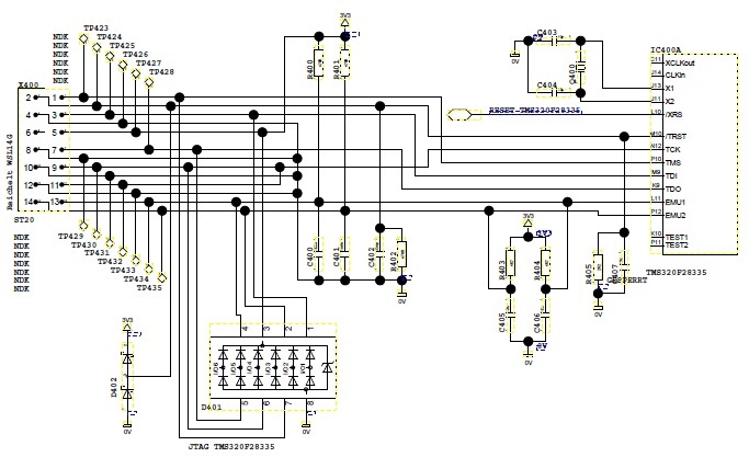
    Can you confirm you have a Pull Down on TRSTn and Pull Up on EMU0/1? If so, what is the value of the pull resistor? If JTAG connected fixes things it may be that we are entering a scan/test mode if TRSTn is toggling from low to high when things get hot/running.

    Matt
  •  Hallo Matt,

    yes we have Pull Down on TRST, about 390 Ohm, and Pull UP at EMU0/1 at about 430 Ohm.

    I attach the schematic of JTAG.

    br Ralf

  • Ralf,
    Thanks for the confirmation, those values should be more than sufficient to keep the pins at the correct level when JTAG head is no connected.

    I see that you are using the XTAL input, can you share if XCLKIN input is grounded(above doesn't show the trace). These inputs are OR'd downstream to for the input clock. The unused source needs to be grounded to avoid spurious glitches on the clock input.

    Can you comment on the value of XTAL as well as final CPU clock post PLL multiplication?

    Best,
    Matthew
  • Ralf,
    One more thing to consider if JTAG/CCS helps this is un-initialized SRAM in standalone mode. When CCS is active the GEL or other setting can take of initializing the SRAM contents for you(in the background). When switching to standalone this is no longer the case and you're program will need to do so. Relating this to temperature may be that a certain word comes up from reset as a 1 or a 0 and this changes over temp.

    Just one more thing to consider.

    Matt
  • Hallo Matt,

    I can confirm, that the XCLKin PIN-J14 is open, could this cause the error?

    We use 30MHz crystal oscilllator, CPU frequency is 150MHz.

  • Ralf,
    This could be the cause of the error. The X1/X2 and XCLKin paths are simply OR'd inside the device. There is a recommendation in the DS to ground the unused clock input(in this case XCLKin) to avoid noise spurs from coupling onto the clock.

    From the history it looks like you are using the BGA package, is the XCLKin pin available on your PCB to ground with a wire to see if this fixes the problem?

    Matt
  • Hallo,

    at the moment we have connected the CLKIN PIN to GND, but the error occurs again. THis is not the solution.

    But the Problem with EPWM is solved, the main problem is another.

    When we start the PWM, our communication from the master, which is a Stellaris via MCBSP to our F28335 is creating an error.

    We always transfer 32-Bytes with DMA support, this works for 2 commands, but when starting the PWM with:

    void StartFOC(void){
        EPwm1Regs.ETCLR.all = 0xD;
        // Set Event-Trigger
        EPwm1Regs.ETSEL.bit.INTSEL = 0x1;    // Interrupt on counter equal to zero
        EPwm1Regs.ETSEL.bit.INTEN = 1;
        
        EPwm1Regs.ETPS.bit.INTPRD = 1;    // do every interrupt
    }

    the received data from MCBSP are shifted for one byte, so the received data are wrong.

    All configuration of the EPWM modul has been done at program start so far.

    Any idea?

  • Hallo again,

    at the moment we have a working solution, which is that we start the EPWM modul with:

    void PWMEnable(void){
        //only enable, if no error was detected
        if(tEpwmMode.usErrFlag == 0){    
            EALLOW;
            EPwm2Regs.TZCLR.bit.OST = 1; // sets the outputs defined to zero
            EPwm1Regs.TZCLR.bit.OST = 1;
            EPwm4Regs.TZCLR.bit.OST = 1;
            EPwm3Regs.TZCLR.bit.OST = 1;
            EPwm6Regs.TZCLR.bit.OST = 1;
            EPwm5Regs.TZCLR.bit.OST = 1;
            EDIS;
        }
    }

    and:

    // starts the FieldOriented Interrupt all 20µs

    void StartFOC(void){
        EPwm1Regs.ETCLR.all = 0xD;
        // Set Event-Trigger
        EPwm1Regs.ETSEL.bit.INTSEL = 0x1;    // Interrupt on counter equal to zero
        EPwm1Regs.ETSEL.bit.INTEN = 1;
        
        EPwm1Regs.ETPS.bit.INTPRD = FOC_BERECHNUNG_ALLE_X_MAL;    //Alle 3 Perioden Interrupt ausführen
    }

    before the first command from the µC-1 is coming in via the MSBCP with DMA transfer.

    In this case all pcbs are working fine.

    But we do not know, what could cause the error when doing the above code later.

    Could there be an influence from this code to the MCBSP-DMA modul?

    br Ralf