This thread has been locked.

If you have a related question, please click the "Ask a related question" button in the top right corner. The newly created question will be automatically linked to this question.

TMS320F28335 ADC Accuracy issue

Other Parts Discussed in Thread: TMS320F28335, TMS570LS3137

Hello,

We are using TMS320F28335 processor in custom board and measuring the ADC accuracy.

One of the analog ADC channel input is connected to precise voltage reference of 1.5Vdc for measuring the ADC conversion accuracy.

But we are getting about 20 to 30 counts variation and could not understand why the ADC counts are jumping about 30 every conversion.

Note that the 1.5Vdc is connected through opamp based 2nd order low pass filter.

We have tried oversampling method and still getting 30 counts variation.

We would like to know what is the expected count variation in standard board or EVAL board ?

In the same custom board we have another processor (TMS570LS3137) which is reading stable ADC counts (max 4 counts vairation) when we read the same 1.5Vc ref

regards,

johnson

  • Hi Johnson,

    Yes, the variations you're observing tends to occur. Apart from low pass filters I personally go for averaging of these adc samples to further bring down these deviations.

    Regards,
    Gautam
  • Hi Johnson,

    What is the ACQPS (acquisition window size) that you have chosen?   Does increasing the ACQPS improve the performance?


    Thank you,
    Brett

  • Hi Johnson,
    In addition to the S+H window duration, what speed is the ADC clock? What are the values of SYSCLK , HSPCLK, ADCLKPS, and CLKPS?
  • Thanks Devin, Brett for your attention.

    ACQPS (acquisition window size) = 3 ( we have tried 7 also, but no change )

    SYSCLK = 150MHz
    HSPCLK (HSPCLK= 011) = 25MHz
    ADCLKPS (ADCCLKPS[3:0] = 0000) = 25 MHz
    and ADCCLK (CPS = 0) = 25 MHz


    regards,
    johnson
  • Hi Johnson,

    A few more...

    Are you using simultaneous sampling mode or sequential?

    Continuous conversion mode?

    Is XCLKOUT enabled to a pin?

    Regards,

    Joe

  • Hi Joe,

    We are using sequential sampling mode

    No Continuous conversion, (using start /stop conversion)

    XCLKOUT is enabled and it is 75MHz, used for external SSRAM. etc

    regards,
    johnson
  • Yes, it does improve the performance but will slow down the conversion rate.
  • Hi Johnson,

    I know XCLKOUT is needed for your system, but can you disable it as an experiment to see if that is where the noise is coming from?

  • Hi Joe,Yes, we did, still getting the variations.regards,johnson
  • And I presume you have followed the DS guidelines for REFP, REFM, and RESEXT external connections? If external reference mode is used, what is providing the reference voltage?
  • Joe, 

    Yes, we have followed DS guidelines for REFP. REFM, RESEXT.

    we are using internal reference, so ADCREFIN is connected to GND

    regards,

    johnson

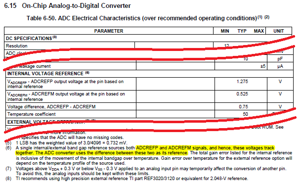
  • Is it possible to read the internal reference voltage instead of external analog input?
  • Johnson,

    Are you able to observe the ADC input pin with a scope while the ADC is converting the op-amp output? There might be some voltage disturbance introduced at the input when the ADC S/H capacitor is connected.

    -Tommy
  • Johnson,

    REFP-REFM is the reference voltage used by the converter.  Looking at the stability of these two pins should be a good indication of the reference stability.

  • Tommy,

    Yes, you are correct. it introduces noise spikes when ADC is sampling.

    Have gone through Hardware guideline document (spraas1b.pdf) and it says we need have external RC for flywheel.

    I tried 50 Ohm and 33pF combination, and converted analog variations are reduced. Now noise variation is about 8 counts.

    We are not using any RC for TMS570LS3137 ADC inputs but we are getting stable ADC counts.

    My question, even 1.5Vdc is connected through opamp based 2nd order low pass filter, still Do we need to use RC at ADC input for stable ADC counts? or anything can be done at software since it is difficult to change at hardware level?

    Note that we are using 16 analog channel for processing and just one channel is connected to stable source.


    regards,
    johnson
  • Johnson,

    The way I think of it is that the internal ADC S/H cap voltage needs to be stable by the time the S/H switch is disconnected. I would assume that the voltage at the input pin would also need to be stable in order for the S/H cap to settle.

    If there is measurable disturbance at the pin, the results can be improved by speeding up the response/settling time of the external voltage source, or the ACQPS can be extended to give the external source more time to settle.

    I'm not an expert with either of these devices so I had to consult the datasheets. It looks like the S/H window for TMS570LS3137 is 200ns, whereas the S/H window for F28335 is 40ns when ACQPS=0. If the devices are configured with these S/H windows, it might explain why the same circuit works on TMS570LS3137 with 200ns S/H, but might look unstable on F28335 with 40ns S/H.

    If you can afford a larger ACQPS on F28335, I would recommend experimenting with that variable first.

    If you have an active low pass filter, you can also try to reduce the magnitude of any low pass filter RC components that touch the ADC pin so that the filter output can respond faster to the voltage disturbance.

    If you have a passive low pass filter, you can try to increase the size of the flywheel cap. This may introduce some offset to the measured voltage, but I would expect improved stability.

    -Tommy
  • Thank you All for the support.

    Based on the experiment, we found that external RC at the ADC inputs make stabel ADC conversion about 1 to 2 variations.

    Basically RC works as flywheel circuit as per TMS320 ADC application note

    regards,
    johnson