This thread has been locked.

If you have a related question, please click the "Ask a related question" button in the top right corner. The newly created question will be automatically linked to this question.

TMS320F28377D - Internal Temp Sensor, ADC Channel Questions

Other Parts Discussed in Thread: TMS320F28377D, CONTROLSUITE

Hi!

I am using the TMX320F28377D device (since the TMS320F28377D has not been released to production), and I had 3 questions.

  1. Internal Temp Sensor

I'm using the internal temperature sensor, and there is very little documentation about its use or accuracy. The TI support page states some dies may be +/-10 degree accuracy, and some older dies might be +/-20 degrees, but it does not specifically define which die versions these are. The Slope is unspecified, but the support pages also state it should be 250 degreesC per volt. Even with this information, the results are inconsistent between my boards. Does anyone have any additional information about this?

2. ADC Sequencers

I am using most of the ADC channels, at a fairly high rate, and I have the ADC sequence synchronized to the EPWM. After the sequencer is triggered, I have to wait ~2us for all 4 sequencers to show as complete – by verifying all 4 ADCBSY flags; however even after all 4 sequencers show as not busy, I still have to wait ~1us to read the ADCs otherwise the readings are erratic. I could not find another method for insuring the ADCs were complete except using ADCBSY, however they are not truly complete because I still have to 1us to read them. Does this extra 1us make sense to you, or should I be using another flag to insure the ADCs are complete?

3. Switching between ADC Modes (12- and 16-bit modes)

I'll be using the ADCs in 16 bit mode for some readings and in 12 bit mode for others, but switching the ADC mode before each reading produced erratic results. To fix this I simply left the ADCs in 12 bit mode. Do you know if there is a problem with switching 12/16-bit modes between readings?

Thank you for your help in advance.

James

  • Hi James,

    Similar to Piccolo series devices F2802x, F2803x, F2806x, and F2805x, automated testing at the TI factory will populate the OTP of each F28377xD device with a slope and offset that can be used to correlate temperature sensor readings with absolute temperature. This functionality is not yet provided in the device header files in ControlSUITE. Note that other forum pages which discuss temperature sensor accuracy or calibration values from these Piccolo devices do not apply to F2837xD.

    See the ControlSUTE examples for ADC usage. The best way to go about determining when the ADC samples are complete is to set the ADC in late interrupt mode and then trigger an ADC interrupt flag on the last conversion in a sequence. You can either poll this flag with the CPU or allow the signal to propagate to the PIE and cause an interrupt.

    Switching ADC modes should only be done when the ADCs are idle and should only be done using the AdcSetMode function provided in the TI header files in ControlSUITE. No delay time is necessary when switching modes. Note that 12-bit mode only supports single-ended signaling and 16-bit mode only supports differential signaling, so you also need to switch the signal mode when you change the resolution.
  • Hi Devin,

    Thanks for your quick, detailed response.

    Could you elaborate about the functionality of the temperature sensor and when this will be provided in the header files in ControlSUITE?

    Also, are there any additional references about using this temp sensor that I am overlooking? There are only a few parameters given in the datasheet and minimal discussion about it in the TRM.

    Thanks again,

    James
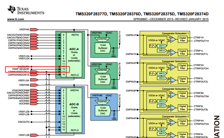
  • The temp sensor is connected to internal ADC channel A13:

    Sampling that channel will produce an ADC conversion result correlated to the device junction temperature.  Device process variation will greatly affect how sensor readings correlate to a particular temperature, so you need some calibration data to interpret the reading.  On Piccolo devices like F2803x, we provide a function in _TempSensorConv.c that  turns the raw ADC reading into a degrees C value:

    //This function uses the reference data stored in OTP to convert the raw temperature
    //sensor reading into degrees C
    int16 GetTemperatureC(int16 sensorSample)

    Current TMX devices may or may not have valid calibration data.  All TMS devices will certainly have valid data and we will provide the functions in ControlSUITE before the device becomes TMS, but I don't have a good estimate of exactly when each of these will be available.

  • Sirs,Can I ask your plan to release the [_TempSensorConv.c] for F28377D . . . ?
    My customer requested that. A sooer release would be highly apprciated.

  • Hi Hideaki,
    We don't have a specific release date yet. I will try to update you when this becomes available.
  • Hi Hideaki,
    Tentatively, temp. sensor example code will come out in a mid-august ControlSUITE release. Current TMX parts will not have the correct OTP calibration data for this to work correctly, but TMS parts will have the correct calibration data (TMX parts shipped between now and TMS time may have correct calibration data).
    There will also be a mechanism to determine if your device has correct calibration values, for which we will also release the details when we release the software examples.
  • I appreciate your update. I will inform that to my customer.-n
  • Hi Hideaki,
    Another update: the temp sensor example code will not be in the August ControlSUITE release, but instead in the September release. I don't think many or any devices will ship with TMX designation that have correct temp. sensor calibration data, but all TMS parts will have the correct data in them.
  • Thank you. Your input was shared with my customer.
  • Hi Devin,
    I shared your sample code with my customer. Thank you very much.

    C:\ti\controlSUITE\device_support\F2837xD\v170\F2837xD_examples_Cpu1\adc_soc_epwm_tempsensor\cpu01