This thread has been locked.

If you have a related question, please click the "Ask a related question" button in the top right corner. The newly created question will be automatically linked to this question.

TMS320F28335: ePWM pulse manipulation

Part Number: TMS320F28335

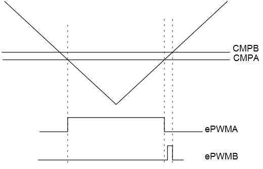
I need to generate a bootstrap charging pulse for a synchronous buck regulator, implemented using F28335 processor. To do this, I need to generate a small pulse on ePWM1B channel, right after the pulse on ePWM1A has ended. Something like this:

Is there any way to generate something like this from the ePWM module on the processor? I have tried a few dead band settings and set/clear settings for ePWM1A and ePWM1B, but have not been successful. Please note there is a small dead time between the ePWM1A pulse and the bootstrap pulse on ePWM1B. The dead time has must be generated to avoid shoot through in the converter.

  • Hi Rohit,

    Can you share what settings you are currently using to initialize your epwm module.
  • Counter mode: Up down

    ePWM1A:
    Set when CMPA = Counter when downcounting
    Reset when CMPA=Counter when upcounting

    ePWMB:
    Set when CMPA=Counter when upcounting
    Clear when CMPB=Counter when downcountig

    Note that CMPB is slightly more than CMPA in value, so the pulse width of ePWMB is going to be very small, as desired.

    The above settings will create pulses on ePWMA and ePWMB as I want to, except for the dead time/dead band.

    Now for the dead band, the active HIGH complementary or active LOW complimentary settings are not relevant because they will generate complimentary pulses for ePWMA and ePWMB, which is not the case here (ePWMB remains OFF for most of the time, except a tiny pulse).

    I do not know what settings to use, to obtain the dead band between the pulses as described above.
  • Hi Rohit,

    I guess you can generate 2 pwm pulses using another ePWM module. Keep these modules synchronized. You can generate these 2 pwm pulses properly and then do some necessary logic operations such as AND, OR etc to these 2 pulses to get your desired signals.

    ePWM is basically based on the duty cycle control. Another way to do this is probably the 0,1 based control. I think this can help too.

    However the first method is preferred if pwm channels are enough for your application.

    Cheers,

    Javy

  • Hi Rohit,

    I tried using different settings for DBCTL register but was not able to generate a deadband as required. I think the other option can be to use a GPIO pin to generate your required small signal.
  • @Ankit
    This will not work, because a GPIO might not be synchronized very well with the PWM modules.

    Regarding JIANWEI's suggestion, the problem is that I am using 4 PWM channels already, for a multi-leg interleaved buck converter. Therefore, I would need a total of 8 channels to do this, which is more than the 6 channels on the processor. I suppose that the best way to do so is to generate PWM pulses without dead band, as I described in the third post in this thread and then use a hardware dead-band circuit.
  • actually 28335 has 6 epwm modules which can generate 12 pwm signals (channels).
  • Yes, I understand that each of the six PWM modules can generate 2 signals. The problem is however, that I am unable to use the two channels in one PWM module to generate the pulses in a desired fashion with a dead band. This could mean that I can use two PWM modules with a phase shift equal to the dead band between them, to generate the pulses for upper and lower switch respectively. However, this means that I need a total of 8 PWM modules, to generate a total of eight pulses in the desired manner. This however is not a possibility since there are only six modules. My mistake for using the word channel where I should have used the word module.
  • it might not be a good idea to change the controller. but you can if you have to. I am using 28377d which has 12 epwm modules. this might be suitable for you.

    Or you can implement the deadband using hardware to save pwm modules.

    again, as i mentioned previously, you can choose to use 0,1 based control method with epwm modules. more details can be referred to the epwm TRM of 28335.

    good luck
  • oh, the updated vesion of 28377 is now 28379, although they are pretty similar in most of functions.
  • Hi, changing the controller is not an option as of now. But what is the 0,1 based control method you speak of? Could you please describe briefly?
  • Hi Rohit, all,

    This is absolutely possible with the F2833x devices. Here's how you can achieve this.

    Terminology:

    CxD: Compare x register match when counter is counting down

    CxU: Compare x register match when counter is counting up

    Settings:

    PWMA settings: SET on CAD, CLEAR on CAU

    PWMB settings: SET on CBU, CLEAR on CAU.

    Dead-band settings: DBCTL[IN_MODE] = 10b (apply RED to PWMA and FED to PWMB), DBCTL[POLSEL] = 10b (PWMB is inverted).

    I hope this helps.

    Hrishi

  • well, you can control the real-time switch states, 0 for off and 1 for on for example, ranther than control the duty cycle. this requires high 'pwm' frequency to improve the precision. briefly your CMPA is either TBPRD or 0, i.e. duty cycle is either 100 or 0. These shoudl follow your real-time control algorithm outout. This is just suggestion, you should check it out to see if it is fine for you application. Dettails to implement this may be found in the technical reference mannual and datasheet
  • Thanks.
    yes the dead band setting help. this would depend on the value of that 'shift'
  • Hi Hrishi, yes this setting works. Thank you. I have one more question. I need to have the ePWM in this setting for some time during converter startup, however after that, I need to have the ePWM configured as active high complimentary, with ePWMA as the source for both RED and FED. Is this possible to do? I mean that the ePWM modules are typically configured in a project and then left as that. Can I actually have it in code so that the ePWM dead band settings can be changed after some time of startup?
  • Hi, Can anyone answer the question in my post above? Please help.
  • Rohit,

    We do not recommend changing DBCTL registers during operation on these devices as the DBCTL register is not shadowed. These registers have shadow loading on our newer devices (TMS320F2837x, F2804x) exactly for the purpose of dynamic configuration changes, as is the case here.

    Hrishi

  • I see. But if we do this anyway, what are the worst case scenarios? Could you please tell?
  • You can make this work if you are careful about the point in time relative to PWM switching cycle where you make the switch. The worst case scenarios are application/power-stage specific and will depend on your overall system implementation.
  • I see. Well, basically, we are thinking of implementing this while also having a NAND lockout on the PWM signal outputs, to avoid shoot through.

    Alternatively, we are thinking of bypassing the dead band in the ePWM module altogether and generate dead band outside, along with the lockout circuit. In this case as well, the ePWMB would have to be changed to trigger from CMPA during normal operation and trigger from CMPB during startup. Does this option seem safer?