This thread has been locked.

If you have a related question, please click the "Ask a related question" button in the top right corner. The newly created question will be automatically linked to this question.

CCS/F28M35H52C: Adapting an Example C2000 Program for my New Hardware

Part Number: F28M35H52C
Other Parts Discussed in Thread: CONTROLSUITE

Tool/software: Code Composer Studio

I've just received a new PCB using the F28M35H52C in a design which is based on the F28M35x ControlCard but some of the GPIO has been moved around.  I am trying to get a simple blinky program running (I made it work on the F28M35x ControlCard) but I can't get my LED to blink.  What I've done so far is as follows:

1. I loaded the blinky_dc_c28 and blinky_dc_m3 programs into CC7 and was able to compile them

2. I then created my own my_pinout.h file that contains alternative #define statements for one LED...

#define DS_LED_0_DIR_REG GpioG1CtrlRegs.GPADIR.bit.GPIO29
#define DS_LED_0_DAT_REG GpioG1DataRegs.GPADAT.bit.GPIO29

Note that I've prefixed with "DS_" and the changes to these statements are that GPIO70 was changed to GPIO29 and that threw an error saying that there was no GPIO29 in GPCD so I looked it up and changed GPCD to GPCA and then changed the LED... statements for LED0 to my own DS_LED... statements in blinky_dc_C28  which got the code to compile.

3. I was able to load both the M3 and C28 code into my new board.

4. I then used the debug>concertocard.ccxml dialogue and was able to connect to both cores and control them both to running but my LED does not flash.  I scoped the GPIO29 output pin and it's permanently low. I scoped the X1/X2 pins and see a nice clean 20 MHz clock signal.

What I was thinking I needed to do is to create my own set_pinout.h file with all my GPIO and peripherals redefined in it but now I'm suspecting that there more to change to get each GPIO pin switched over - I'd appreciates some guidance. Maybe I need to create a new targetconfiguration.ccxml file? I played with that idea but can;t see how to make the .ccxml file own the example programs.

Ted

  • It sounds like you created a new pinout file for the C28, but did you create one for the M3 as well? I believe there's some code in the M3 project that gives ownership of the pin to the C28. You'll want to make sure that's updated for your new pin too.

    Whitney
  • I spent more time looking at this, the issue is likely in the setup of the pin permissions.  

    Basically, all I am trying to do is change the standard dual core blinky program to use GPIO29 (PE5) as the output that drives LED0  from the pin example program uses which is GPIO70 (PC6).

    In blinky_dc_c28.c I changed the following

    Lines 46 and 48 refere to LED_0_DIR_REG and LED_0_DAT_REG so I looked up the definitions and found they were in F28M35x_set_pinout.h so I modiified the references as follows:

    //#define LED_0_DIR_REG GpioG1CtrlRegs.GPCDIR.bit.GPIO70
    //#define LED_0_DAT_REG GpioG1DataRegs.GPCDAT.bit.GPIO70
    #define LED_0_DIR_REG GpioG1CtrlRegs.GPADIR.bit.GPIO29
    #define LED_0_DAT_REG GpioG1DataRegs.GPADAT.bit.GPIO29

    Note the original lines are commented out.

    LED_0_DAT_REG is referenced again in the for(;;) loop so I think that's all there is for the c28 program.

    ------

    In the blinky_dc_m3.c program I made the following changes...

    Line 104 through 114 refer to LED_0_PERIPH, LED_0_BASE, and LED_0_PIN which are defined in set_pinout_f28m35x.h which I modified as follows:

    //*****************************************************************************
    // GPIO for the user LEDs
    //*****************************************************************************
    //#define LED_0_PERIPH SYSCTL_PERIPH_GPIOC
    #define LED_0_PERIPH SYSCTL_PERIPH_GPIOE // TM GPIO29 is PE5
    //#define LED_0_BASE GPIO_PORTC_BASE
    #define LED_0_BASE GPIO_PORTE_BASE
    //#define LED_0_PIN GPIO_PIN_6
    #define LED_0_PIN GPIO_PIN_5

    #define LED_1_PERIPH SYSCTL_PERIPH_GPIOC
    #define LED_1_BASE GPIO_PORTC_BASE
    #define LED_1_PIN GPIO_PIN_7

    note I've lcommented out the original lines

    the blinky_dc_m3.c program gives control of LED_0 to the C28 core at line 109 as follows: 

    // Give C28 control of Port C pin 6
    GPIOPinConfigureCoreSelect(LED_0_BASE, LED_0_PIN, GPIO_PIN_C_CORE_SELECT);

    but the changes made to set_pinout_f28m35x.h should take care of the fact that my LED0 is on GPIO29 instead of GPIO70

    the rest of blinky_dc_m3.c goes on to set up for LED3 and blink that LED but that should not affect my program.

    I tried it, it does not work.  I'm sure my LED is good and connected the right way round - the anode is connected to GPIO29 and the cathode is connected to ground via a 150 Ohm resistor.

    I reloaded everything and made the changes again from scratch to make sure I hadn't messed something up in the files. It still doesn't work.

    I'm stuck ;(

  • Hmm, I just tried scoping the LED1 pin on the processor and there is no activity - stuck at zero volts. I can see the 20 MHz clock on the X1 and X2 pins and CCS says it's connecting, programming, and and running - I can also pause the program and see that it's going around the loop. What tests can I do to view the status of the output mux registers to make sure they are set as outputs. Or is there something on my code setup that's missing?
  • Your code changes all sound correct to me. I'm not seeing an issue yet. I don't suspect there's an issue with your custom board, but out of curiosity, have you tried running the code on the cCARD and seeing if the 29 pin toggles there?

    You mentioned wanting to check the registers--in CCS you can go to View->Registers to open a panel that will let you view the register contents as you debug. It'll show the registers for whichever core you have selected in the Debug panel.

    Whitney
  • Thanks, the customer has now confessed that this chip may have been subject to overvoltage - perhaps as much as 12 volts.  I'm going to replace the chip on the PCB.

  • New processor fitted, it's exactly the same.  I'll keep looking, thinking of writing code from scratch but this is frustrating.

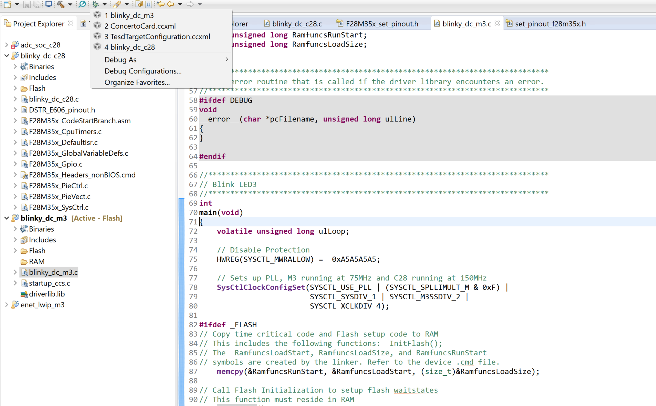
  • I think there's a problem with my understanding of the setup of the CCS environment.  I can get my board to run but only under a specific  sequence of actions.  If you can look at my screen capture below what I have is the dual example of blinky which has actually been set back to the standard settings and I've connected an LED to GPIO71 (plus I'm able to probe GPIO70 with a scope) anyway I can see that both are 'flashing' when I get it to run but I can only make it run by doing the following steps:

    1. Click on either the debug button on the toolbar or item 1: blinky_dc_m3 - it then tells me it's loading_program blinky_dc_m3.out

    2. I then see the 2 cores in the debug window, the m3 is connected but suspended and the C28 is disconnected

    3. I then run the m3 section and it says "running" (the C28 shows "disconnected")

    4. I then right click on the C28 line and select connect target, I then see the C28 core shows as "suspended"

    5. With the C28 section selected, I click on the run button and both cores then show running and the GPIO ports start flashing - neither flashes before this step

    6. I can then hit the stop button and I drop out of debugging in the CCS session but the hardware keeps running with the LED flashing

    7. If I power cycle the PCB, it doesn't start (flash) (it doesn't matter whether the XDS100V2 is connected or not

    I thought that once code was running, that it would start whenever the hardware was power cycled.  I also thought that I should be running by selecting one of the .ccxml files - I tried to create my own but it doesn't work, nor does the once that was there when I loaded the project, the ConcertoCard.ccxml - these files seem to load and control the cores but when I pause them while they show "running", the procesor cores seem to be in idle.

    Can you shed any light on what I'm doing wrong from this description? Let me know if you want me to do further tests.

  • Hi Ted,

    What do you have your boot mode pins set to? This could likely be the issue since having an emulator connected will override the pin settings.

    Regards,
    Kris
  • This is likely the issue, the hardware designer has not provided pull ups or pull downs on the Boot pins - is there any other way to set these or can I reallocate the boot pins to other GPIOs?

  • Hi Ted,

    I believe you're stuck here. You may want to try to do some jumper wire soldering before you do a board spin just to make sure it is the issue. I'll contact some of our boot-flow experts to jump in here. They may have some debug steps to help confirm the issue.

    Regards,
    Kris
  • Ted

    Your description of the steps to debug is correct. Once M3 is running, it will wait until C28 is ready to send IPC message to tell C28 how to boot.

    This definitely sounds like the boot GPIOs aren't set for flash. Do you know what their state is?

    You can switch what GPIOs are used for boot but it's a one time change since its OTP. See more details in the TRM below (chapter 6.3.1). If this region has already been written to, then you won't be able use that method. But again, only use this if you are willing to perminately change the GPIOs used for boot.

    http://www.ti.com/lit/spruh22

    Best regards
    Chris
  • Update.  The client realized they'd given me an old prototype chip so they sent me one that's Revision 1 silicon and I've swapped that one onto the PCB.  Now I should be able to solder resistors to unused pins to implement the missing Boot Mode pins and, given that's a one-time (OTP) operation, I'd like some guidance on how to do that please.

    The Reference Manual (spruh22h.pdf) says on page 539... "To change the default boot mode pin to GPIOx, program GPIOx+1 in the corresponding bit field."

    I understand that I need to program (GPIOx+1) numbers into the Bmode1,2,3,4 registers but how do I actually do that?  Is it done from within CCS?

    Thanks in advance.

  • So now I have fitted a replacement Rev 1 chip which means that I should be able to assign the boot mode pins to spare GPIO pins; I realize that, to change the default boot mode pin to GPIOx, I need to program GPIOx+1 in the corresponding bit field of the Bmode_pinx pins but how do I actually do that? Is it done somehow through Code Composer Studio?

    Thanks in advance.

  • Ted

    You program OTP the same as you program flash except that you can only do it once. Use the linker to specify the location in OTP and assign what you want programmed there. Can assign variables to that section with pragmas (See chapter 6 www.ti.com/lit/spru514 )

    You can use CCS to view and see that your values are programmed correctly.

    Best regards
    Chris
  • Thanks, I don't understand the suggestion to "use the linker".  Do you mean that I just add the pragma statements to my code and then flash the device?

  • Christopher, I found this discussion in an older thread
    e2e.ti.com/.../312626
    and now I'm concerned that I do this correctly because I risk ruining my chip which has already been changed out twice on this PCB and a 3rd time would be pushing things for the PCB tracks to survive and THAT would be a disaster.

    I realize exactly what values I need to put in the Bootmode registers, I want to make GPIO68, 69, 70, 71 into Bmode_pin1,2,3,4 respectively. These pins are now set up put pull ups on 68, 69, and 70 and pull down on 71. Questions:

    1. If I add a pragma statement, does it need to set all 4 values at once?
    2. Please can you please give me the syntax of that pragma statement?
    3. Does the pragma statement go in my main.c code? If not where does it go?
    4. How will this affect production? All new PCBs will need to have the Bmode_pinx values set before they will work.

    Thanks,
  • Ted

    Yes, you either create a new variable in your code and use the pragma to assign that variable to section that you setup in linker. Alternatively, you could create a ASM file in your project and setup a section that way. This still requires editing the linker file to assign that data to the correct section in memory.

    Example pragma (It can go into whatever C file makes sense):
    #pragmaDATA_SECTION(nameOfVariable, ".myNewSection")
    unsigned long nameOfVariable = 0xABCDABCD;

    You can read more about in at chapter 6 www.ti.com/lit/spru514

    For an ASM file, you can do something like
    .sect ".myNewSection"
    .word 0xABCDABCD

    Example linker:
    --retain '(.myNewSection)'
    MEMORY
    {
    OTP : origin =0x00000000, length = 0x4 //Just example, not correct address
    }
    SECTIONS
    {
    .myNewSection : > OTP
    }

    Suggest first placing data in RAM/Flash (not OTP) to see that the value is being programmed to the correctly and specified how you want.

    Your devices won't use these pins until their OTP is configured for these new pins.

    Best regards
    Chris
  • I fitted a new chip, revision 1 which should allow the boot mode pins to be reassigned to unused pins, I've chosen GPIO68, 69, 70, and 71 which I want to assign to Bmode_pins 1,2,3, and 4 respectively. I seem to be able to load code to the chip and communicate with it from CCS but the oscillator doesn't seem to be running - I can't see any signals when I scope the X1/X2 pins.

    I've got some advice on programming the OTP memory using pragma statements but I'm worried that the device isn't even running even although debug seems to indicate it is.

    Any suggestions for tests or how to program the OTP are welcome - isn't there a flash tool that allows me to see the OTP values?

    I'm close to giving up on this.
  • Ted,

    Chris is Out of Office and I'm looking at this thread today. There are other customers who did what you are trying to do, if it helps your confidence :-)

    e2e.ti.com/.../339389

    the above thread has details on how to change the boot mode select pins on F28M35x. Also the above thread has a link to another user who went through the steps to program the data into OTP, just like you are trying to do.

    The documented OTP regions should be available in memory window and you can also view the location values in expressions window.

    Hope this helps.

    Also I'm not sure how this affects the X1/X2, are you providing a clock from external oscillator? Also scope the XRSn pin, the OTP has ECC so if there is any mess up with the values while being programmed will result in an ECC error and device could go into back to back resets.

    OTP is one time programmable, so you will have to be careful, hope you have some extra parts lying around for your experiments.


    Best regards
    Santosh Athuru
  • Thanks Santosh, I'll read the link you gave and report back on how I do.
  • So I added the #pragma statement to my C file and it builds, my extra lines look like this

    #pragma DATA_SECTION(TedsVariable,".TedsNewSection")
    unsigned long TedsVariable = 0x48474645;

    I am pretty sure that what I need to do is to store 0x48474645 into location 0x680824 to make GPIO71,70,69,68 be Boot pins 4,3,2,1 respectively - anyone who can confirm that, please do.

    I realize that I need to open and edit the linker file to add the instruction to tell it where to store my new variable and that you're advising me to test it in RAM or a Flash Location first.

    My question is, from within CCS, where do I go to find, open, and edit the Linker file?

    Thanks.

  • Ted

    Yes, that pragma setup looks correct.

    I can't specifically say where your linker file is in your project. Linkers end in ".cmd". If you don't see it in the project explorer, may have to check the project properties either under general or the "C2000 linker" File Search Path section.

    Best regards
    Chris
  • Chris,

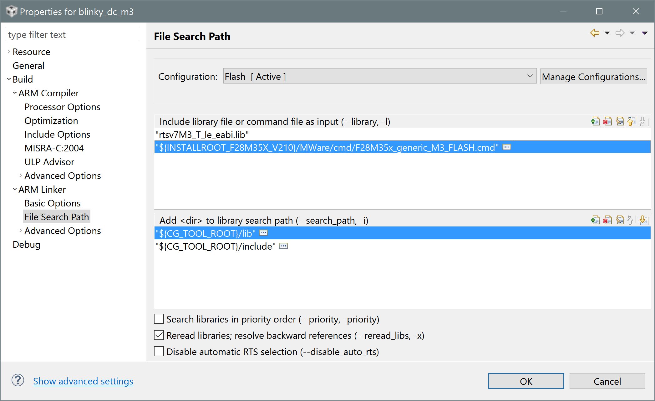
    I'm running CCS 7.2 and I'm using the Dual Blinky M3 example (default install location on my PC), the attached picture shows a page from the options dialog box, please confirm that I'm right in thinking that the file at C:\ti\controlSUITE\device_support\f28m35x\v210\MWare\cmd\F28M35x_generic_M3_FLASH.cmd is the linker file I need to edit.

    It's been suggested that I use a different location other than 0x680824 to first test that I can write the data and see it's written before I actually make the attempt a OTP,  I went into the data sheet for the processor f28m35h52c.pdf and, on page 156 in the memory map section, there's a block from 0068 0818 - 0070 00FF that's 'reserved' so that makes me worry that the write is not going to work without other changes.  Also, can you suggest an area from which to pick an address for the test write?

  • Ted

    Yes, that looks like the right linker for that project.

    You should be able to program OTP just like any other flash section except of course you can only do it once and cannot undo it.
    You can try a test write in RAM or Flash. Such as memory section C2 or C2 or FLASH1/2.

    Best regards
    Chris
  • Chris,

    I looked in the actual link file today and this is the memory section...

    MEMORY
    {
    
        INTVECS (RWX)    : origin = 0x20000000, length = 0x01B0
        C0 (RWX)         : origin = 0x200001B0, length = 0x1E50
        C1 (RWX)         : origin = 0x20002000, length = 0x2000
        BOOT_RSVD (RX)   : origin = 0x20004000, length = 0x0900
        C2_1 (RWX)       : origin = 0x20004900, length = 0x0700
        RESETISR (RWX)   : origin = 0x20005000, length = 0x0008
        C2_2 (RWX)       : origin = 0x20005008, length = 0x0FF8
        C3 (RWX)         : origin = 0x20006000, length = 0x2000
        CTOMRAM (RX)     : origin = 0x2007F000, length = 0x0800
        MTOCRAM (RWX)    : origin = 0x2007F800, length = 0x0800
    	
    	OTPSECLOCK       : origin = 0x00680800, length = 0x0004
        OTP_Reserved1    : origin = 0x00680804, length = 0x0004
        OTP_Reserved2    : origin = 0x00680808, length = 0x0004
        OTP_Z2_FLASH_START_ADDR             : origin = 0x0068080C, length = 0x0004
        OTP_EMACID       : origin = 0x00680810, length = 0x0008
        OTP_Reserved3    : origin = 0x00680818, length = 0x0004
        CUSTOMER_OTP_MAIN_OSC_CLK_FREQ      : origin = 0x0068081C, length = 0x0004
        OTP_Reserved4    : origin = 0x00680820, length = 0x0004
        OTP_BOOT_MODE_GPIO_CONFIGURE        : origin = 0x00680824, length = 0x0004
        OTP_Reserved5    : origin = 0x00680828, length = 0x0004
        OTP_ENTRY_POINT  : origin = 0x0068082C, length = 0x0004
        OTP_Reserved6    : origin = 0x00680830, length = 0x0010
    }

    Note that, in there, there's a "OTP_BOOT_MODE_GPIO_CONFIGURE : origin = 0x00680824, length = 0x0004" so can't I just write in the main code, something like this..

    OTP_BOOT_MODE_GPIO_CONFIGURE = 0x48474645;

    Please advise.

  • Ted

    OTP_BOOT_MODE_GPIO_CONFIGURE is the defined memory range of that region on the device. To place your value there, in the linker "SECTIONS" part of the file, you will do the following:

    .TedsNewSection : > OTP_BOOT_MODE_GPIO_CONFIGURE


    This takes the section you defined for your variable and places it in that memory region. You can just replace OTP_BOOT_MODE_GPIO_CONFIGURE with C2 or C3 for placing in RAM.

    Best regards
    Chris
  • Well it's not working.

    I added my variable, called TedsVariable, assigned it the required value, and edited the .cmd file so that it's stored in TedsNewSection.  I tried to run the program and got no error. so I rebooted without CCS connected and found that the code was not running.  When I reconnected, I tried to look at the contents of 0x680824 or the contents of TedsVariable but I seem unable to see any variables in the Debug watch window... sigh

    Right now I just want to look at the content of the OTP Boot Mode register at 0x680824

    Somewhere I saw that there was a Flash Config GUI tool, might that help?

  • Ted,

    In CCS, when connected and debugging the device, did you try the memory browser (View->Memory Browser)?

    Edit : You might not be able to see it in the memory window without editing the GEL file that gets loaded through your target configuration file. It is likely you are using the gel "f28m35h52c_m3.gel". If you go into your CCS install -> ccs_base -> emulation -> gel and find this file. Open with text editor, and change line 113 to the following:

        GEL_MapAddStr(0x68080C,      0, 0x00100,    "R",   0);        /* OTP BANK 1 Application 2            */

    Save and restart CCS, it should now be visible in the memory window.

    Also, be aware this location has ECC, read more in  "6.5.6 M-Boot ROM User OTP" in the TRM.


    Best regards
    Chris

  • I edited the .gel file and now I can see the contents of the memory, 0x680824 contains 0xFFFFFFFF so clearly my code has not been allowed to write the values to the OTP.  I'll keep trying.

  • I put a breakpoint on my line that assigns 0x48474645 to address 0x680824 but in stepping through my program, I never get there, it appears to be stuck in a C28 system bootloader. Is it possible to use some kind of register editor to program the contents 0x680824?
  • I went back over everything and discovered that I had edited the wrong .cmd file. I had been editing C:/ti/controlSUITE/device_support/f28m35x/v210/MWare/cmd/F28M35x_generic_M3_RAM.cmd instead of
    C:/ti/controlSUITE/device_support/f28m35x/v210/MWare/cmd/F28M35x_generic_M3_FLASH.cmd

    I fixed that and recompiled, I was able to run my code but the contents of 0x680824 are unchanged at FFFFFFFF

    Are you sure that the #pragma statement as follows is going to cause the value 0x48474645 to be written to my variable?
    #pragma DATA_SECTION(TedsVariable,".TedsNewSection")
    unsigned long TedsVariable = 0x48474645;

    Also, when I go into the debugger, the expressions wind now shows TedsVariable but type is "unknown" and Value is "identifier not found: TedsVariable"

    My report from the build is as follows:
    'Invoking: ARM Compiler'
    "C:/ti/ccs_700/ccsv7/tools/compiler/ti-cgt-arm_16.9.0.LTS/bin/armcl" -mv7M3 --code_state=16 -me --include_path="C:/ti/ccs_700/ccsv7/tools/compiler/ti-cgt-arm_16.9.0.LTS/include" --include_path="C:/ti/controlSUITE/device_support/f28m35x/v210/MWare" -g --define=ccs --define="_FLASH" --define=_STANDALONE --diag_suppress=10199 --diag_warning=225 --display_error_number --gen_func_subsections=on --abi=eabi --preproc_with_compile --preproc_dependency="blinky_dc_m3.d" "C:/ti/controlSUITE/device_support/f28m35x/v210/F28M35x_examples_Dual/blinky/m3/blinky_dc_m3.c"
    'Finished building: C:/ti/controlSUITE/device_support/f28m35x/v210/F28M35x_examples_Dual/blinky/m3/blinky_dc_m3.c'
    ' '
    'Building target: blinky_dc_m3.out'
    'Invoking: ARM Linker'
    "C:/ti/ccs_700/ccsv7/tools/compiler/ti-cgt-arm_16.9.0.LTS/bin/armcl" -mv7M3 --code_state=16 -me -g --define=ccs --define="_FLASH" --define=_STANDALONE --diag_suppress=10199 --diag_warning=225 --display_error_number --gen_func_subsections=on --abi=eabi -z -m"blinky_dc_m3.map" --stack_size=256 --heap_size=0 -i"C:/ti/ccs_700/ccsv7/tools/compiler/ti-cgt-arm_16.9.0.LTS/lib" -i"C:/ti/ccs_700/ccsv7/tools/compiler/ti-cgt-arm_16.9.0.LTS/include" --reread_libs --warn_sections --xml_link_info="blinky_dc_m3_linkInfo.xml" --rom_model -o "blinky_dc_m3.out" "./blinky_dc_m3.obj" "./startup_ccs.obj" "C:/ti/controlSUITE/device_support/f28m35x/v210/MWare/driverlib/ccs/Debug/driverlib.lib" -lrtsv7M3_T_le_eabi.lib -l"C:/ti/controlSUITE/device_support/f28m35x/v210/MWare/cmd/F28M35x_generic_M3_FLASH.cmd"
    <Linking>
    warning #10247-D: creating output section "ramfuncs" without a SECTIONS
    specification
    'Finished building target: blinky_dc_m3.out'
    ' '

    **** Build Finished ****
  • I went back over everything and discovered that I had edited the wrong .cmd file. I had been editing C:/ti/controlSUITE/device_support/f28m35x/v210/MWare/cmd/F28M35x_generic_M3_RAM.cmd instead of
    C:/ti/controlSUITE/device_support/f28m35x/v210/MWare/cmd/F28M35x_generic_M3_FLASH.cmd

    I fixed that and recompiled, I was able to run my code but the contents of 0x680824 are unchanged at FFFFFFFF

    Are you sure that the #pragma statement as follows is going to cause the value 0x48474645 to be written to my variable?
    #pragma DATA_SECTION(TedsVariable,".TedsNewSection")
    unsigned long TedsVariable = 0x48474645;

    Also, when I go into the debugger, the expressions window now shows TedsVariable but type is "unknown" and Value is "identifier not found: TedsVariable"

    My report from the build is as follows:
    'Invoking: ARM Compiler'
    "C:/ti/ccs_700/ccsv7/tools/compiler/ti-cgt-arm_16.9.0.LTS/bin/armcl" -mv7M3 --code_state=16 -me --include_path="C:/ti/ccs_700/ccsv7/tools/compiler/ti-cgt-arm_16.9.0.LTS/include" --include_path="C:/ti/controlSUITE/device_support/f28m35x/v210/MWare" -g --define=ccs --define="_FLASH" --define=_STANDALONE --diag_suppress=10199 --diag_warning=225 --display_error_number --gen_func_subsections=on --abi=eabi --preproc_with_compile --preproc_dependency="blinky_dc_m3.d" "C:/ti/controlSUITE/device_support/f28m35x/v210/F28M35x_examples_Dual/blinky/m3/blinky_dc_m3.c"
    'Finished building: C:/ti/controlSUITE/device_support/f28m35x/v210/F28M35x_examples_Dual/blinky/m3/blinky_dc_m3.c'
    ' '
    'Building target: blinky_dc_m3.out'
    'Invoking: ARM Linker'
    "C:/ti/ccs_700/ccsv7/tools/compiler/ti-cgt-arm_16.9.0.LTS/bin/armcl" -mv7M3 --code_state=16 -me -g --define=ccs --define="_FLASH" --define=_STANDALONE --diag_suppress=10199 --diag_warning=225 --display_error_number --gen_func_subsections=on --abi=eabi -z -m"blinky_dc_m3.map" --stack_size=256 --heap_size=0 -i"C:/ti/ccs_700/ccsv7/tools/compiler/ti-cgt-arm_16.9.0.LTS/lib" -i"C:/ti/ccs_700/ccsv7/tools/compiler/ti-cgt-arm_16.9.0.LTS/include" --reread_libs --warn_sections --xml_link_info="blinky_dc_m3_linkInfo.xml" --rom_model -o "blinky_dc_m3.out" "./blinky_dc_m3.obj" "./startup_ccs.obj" "C:/ti/controlSUITE/device_support/f28m35x/v210/MWare/driverlib/ccs/Debug/driverlib.lib" -lrtsv7M3_T_le_eabi.lib -l"C:/ti/controlSUITE/device_support/f28m35x/v210/MWare/cmd/F28M35x_generic_M3_FLASH.cmd"
    <Linking>
    warning #10247-D: creating output section "ramfuncs" without a SECTIONS
    specification
    'Finished building target: blinky_dc_m3.out'
    ' '

    **** Build Finished ****
  • Ted,

    Ted Mawson 3.0 said:
    Are you sure that the #pragma statement as follows is going to cause the value 0x48474645 to be written to my variable?

    #pragma DATA_SECTION(TedsVariable,".TedsNewSection")
    unsigned long TedsVariable = 0x48474645;

    the above is not going to work. What it is doing instead is it is declaring a global variable and placing it in the .TedsNewSection and your runtime initialization code will then try to initialize the variable before the program reaches main and it is not going to work.

    Try adding 'const' to the variable and see if it changes. 

    OR

    you can do what this user did in the below post

    e2e.ti.com/.../312626

    #pragma RETAIN(boot_otp)
    #pragma LOCATION(boot_otp, 0x00680824);
    const unsigned long boot_otp = 0x21212121;

    Hope this helps.

    Best Regards

    Santosh Athuru

  • Clarification: in the above sample code, the value assigned to boot_otp var is shown just as an example and pulled out from the linked forum post. You will have to use the value you came up with.

    Best Regards
    Santosh Athuru
  • Santosh,

    Thanks, I got it to program the OTP.

    Just putting 'const' in front of the variable declaration didn't work but the 3 lines you just posted with the correct value (for me) of 0x48474645 was successful and not my F28M35H52C runs on its own.

  • I got it to work eventually by reprogramming the C2000 to use different boot pins, see e2e.ti.com/.../2350546
  • Santosh solved this issue for me, the relevant link is here e2e.ti.com/.../2350546

    Thanks Santosh
  • Ted,

    thanks for confirming. Please use the forums if you have any further questions or feedback as your project progresses.

    Best Regards
    Santosh Athuru