


Hello:
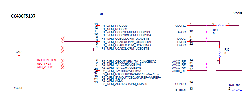
I need help to setup the CC430F5137 to read ADC value from PM_TA1CCR01 and PM_TA1CCR1A ports. The ADC must collect 512 sample per second by using DMA only.
I would like hardware / software setup:
* ADC from PM_TA1CCR0A and PM_TA1CCR1A ports
* Collect 512 samples per second
* Using only DMA
---------------------------- Sample Source Code setup -------------------
#include <msp430.h>
#include <cc430f5137.h>
#include <xdc/std.h>
#include <xdc/runtime/Log.h>
#include <ti/sysbios/BIOS.h>
#include <ti/sysbios/knl/Task.h>
#include <ti/sysbios/knl/Semaphore.h>
/* Semaphore handle defined in task.cfg */
extern const Semaphore_Handle mySem;
unsigned int DMA_DST;
/* Counter incremented by timer interrupt */
volatile UInt tickCount = 0;
/*
* ======== main ========
*/
Void main()
{
WDTCTL = WDTPW+WDTHOLD; // Hold WDT
P1OUT = 0; // P1.0, P1.6 clear
P1DIR |= BIT0 + BIT1 + BIT6; // P1.0 output to LED, P1.6 GND
PMAPPWD = 0x02D52; // Get write-access to port mapping regs
P2MAP6 = PM_TA0CCR1A; // Map TA0CCR1 output to P2.6
PMAPPWD = 0; // Lock port mapping registers
P2DIR |= BIT6; // Output TA0CCR1
P2SEL |= BIT6; // Enable TA0CCR1 functionality
/* Initialize Timer A0 */
TA0CCR0 = 0xFFFE;
TA0CCR1 = 0x8000;
TA0CCTL1 = OUTMOD_3; // CCR1 set/reset mode
TA0CTL = TASSEL_2+MC_1+TACLR; // SMCLK, Up-Mode
/* Initialize REF module */
// Enable 2.5V shared reference, disable temperature sensor to save power
REFCTL0 |= REFMSTR+REFVSEL_2+REFON+REFTCOFF;
/* Initialize ADC12_A */
ADC12CTL0 = ADC12SHT0_15+ADC12MSC+ADC12ON;// Sampling time, MSC, ADC12 on
ADC12CTL1 = ADC12SHS_1+ADC12CONSEQ_2; // Use sampling timer; ADC12MEM0
// Sample-and-hold source = CCI0B =
// TBCCR1 output
// Repeated-single-channel
ADC12MCTL0 = ADC12SREF_0+ADC12INCH_0; // V+=AVcc V-=AVss, A0 channel
ADC12CTL0 |= ADC12ENC;
__delay_cycles(75); // ~75us shared ref. settling time
/* Initialize DMA0 */
DMACTL0 = DMA0TSEL_24; // ADC12IFGx triggered
DMACTL4 = DMARMWDIS; // Read-modify-write disable
DMA0CTL &= ~DMAIFG;
DMA0CTL = DMADT_4+DMAEN+DMADSTINCR_3+DMAIE; // Rpt single tranfer, inc dst, Int
DMA0SZ = 1; // DMA0 size = 1
__data16_write_addr((unsigned short) &DMA0SA,(unsigned long) &ADC12MEM0);
// ... from ADC12MEM0
__data16_write_addr((unsigned short) &DMA0DA,(unsigned long) &DMA_DST);
// ... to destination in RAM
/*
* Print "Hello world" to a log buffer.
*/
Log_info0("Hello world\n");
/*
* Start BIOS.
* Begins task scheduling.
*/
BIOS_start(); /* does not return */
}
//------------------------------------------------------------------------------
// DMA Interrupt Service Routine
//------------------------------------------------------------------------------
void DMA_ISR_fnx(void)
{
switch(__even_in_range(DMAIV,16))
{
case 0: break;
case 2: // DMA0IFG = DMA Channel 0
P1OUT |= BIT0; // Toggle P1.0
break;
case 4: break; // DMA1IFG = DMA Channel 1
case 6: break; // DMA2IFG = DMA Channel 2
case 8: break; // DMA3IFG = DMA Channel 3
case 10: break; // DMA4IFG = DMA Channel 4
case 12: break; // DMA5IFG = DMA Channel 5
case 14: break; // DMA6IFG = DMA Channel 6
case 16: break; // DMA7IFG = DMA Channel 7
default: break;
}
P1OUT &= ~BIT0; // Toggle P1.0
}
----------------------------------------------------------------------------------------------------------
Thank You
Mike

