This thread has been locked.

If you have a related question, please click the "Ask a related question" button in the top right corner. The newly created question will be automatically linked to this question.

BSL_Scripter-MSP430f5435-CP2102 usb2uart module

Other Parts Discussed in Thread: MSP430F5435, MSP430F5438, MSP430F5438A

Hi,

I am using CP2102 based usb2uart module to program MSP430f5435 using BSL_Scripter.exe. But I am experiencing few strange situations. I have been able to communicate between the PC and the MSP using the above module. But when i connect the same module to program the msp using cmd I am getting errors. The connections as given below:

usb2uart  MSP430

TX                 TA0.1

RX                 TA0.0

DTR               RST/NMI

RTS               TEST

VCC                  VCC

GND               GND.

I have just connected the things and in cmd executing the BSL_Scripter.exe filename.txt . Do i need to do anything explicitly to invoke the BSL..?? I assume just by executing the above command in cmd will invoke the BSL and dumps the code to flash memory of msp.

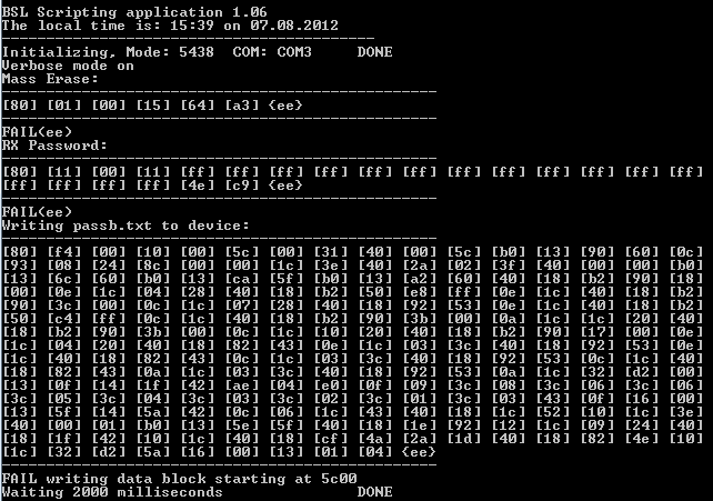
The snapshot of the error looks like below:

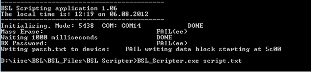
And the code in the script.txt is

MODE 543x_family COM14
MASS_ERASE
DELAY 1000
RX_PASSWORD
RX_DATA_BLOCK passb.txt

Also when i change COM14 to USB in cmd its not showing any error. Even when nothin is connected to the PC.

So can someone please identify where am i going wrong..??

  • Kailash,

    you can check the Launchpad-Based MSP430 UART BSL Interface (Rev. A)  App note for more details on the BSL Hardware connection to the Target device.

    http://www.ti.com/mcu/docs/litabsmultiplefilelist.tsp?sectionId=96&tabId=1502&literatureNumber=slaa535a&docCategoryId=1&familyId=342

    Hope this helps, otherwise please let me know.

    BR,

    Mo.

  • The connections are correct and I ve referred to that document also. Still the staus of the problem I ve posted remains the same. 

    Regards,

    Kailash

  • Kailash V said:
    I assume just by executing the above command in cmd will invoke the BSL and dumps the code to flash memory of msp.

    Yes, this is correct. The BSL scripter will automaticaly generate the BSL entry sequence to invoke the BSL.

    Can you try it with the below settings?

    MODE 5xx COM14
    VERBOSE
    MASS_ERASE
    RX_PASSWORD
    RX_DATA_BLOCK passb.txt
    DELAY 2000

    Also, what is the Vcc voltage level?

    On the usb2uart module, are you able to see the BSL entry sequence on a scope (DTR and RTS lines) when runing the BSL scripter?

    BR,

    Mo.

  • As I am using MSP430f5435 I think MODE should be 543x_family. 

    Vcc Voltage is 3.3V and is there any other way to check the signal in DTR and RTS lines. Becuase i don't have an oscilloscope right now. 

  • when i used verbose the cmd looked like this:

    I ve studied about verbose but did not understand properly. Can you tell in breif about that?

  • when nothing is connected to the laptop and when the code is executed the above screenshot itself is displayed in cmd..?? how is this possible?

  • Hi Kailash,

    Kailash V said:

    when nothing is connected to the laptop and when the code is executed the above screenshot itself is displayed in cmd..?? how is this possible?

     
    Because what you see is basically the data sent by the BSL Scripter. all data which is shown by square brackets [] are basically the data sent by the BSL Scripter, and data sent by the curly brackes {} are data sent by the MSP430 target. In your case the {ee} means basically timeout (BSL Scripter doesn't receive any data from MSP430 target).
    I would suggest you to check the BSL Entry sequence on TEST and RST pin. Or use the SLAA535 refered by Mo above, this should work with MSP430F54xx you are using (I have tested it myself).
  • lhend said:
    BSL Scripter doesn't receive any data from MSP430 target

    Is it a 5435 or a 5435A? The A types require a specific timing which is almso timpossible to do with an USB->serial converter. THe A types can only be programmed through BSL with a real COM port or the LaunchPad BSL 'interface'.

  • Thanks Leo,

    I am using 5435(non-A). 

    BTW MSP430f5435(non-A) is a device with dedicated JTAG pins right? So I have to use TST and RST/NMI pins for entering into the BSL. Am I correct? 

  • Hi Kailash,

    Kailash V said:

    BTW MSP430f5435(non-A) is a device with dedicated JTAG pins right? So I have to use TST and RST/NMI pins for entering into the BSL. Am I correct? 

    The MSP430F54xx non-A and A devices are devices with share JTAG pins. The easiest way to make the difference is basically to see whether the device have TEST pin. If it has TEST pin, it is then categorized as devices with shared JTAG pins. However your second argument is correct, for devices with shared JTAG pins, you need to apply the BSL entry sequence at RST and TEST pin, See the following wiki:

    http://processors.wiki.ti.com/index.php/MSP430_FAQ#How_to_invoke_the_BSL.3F

  • Can someone test MSP430f5435 uart bsl programming? Because I think its not possible to program it through BSL. I somehow managed to enter the BSL by apllying the proper waveforms on tst and rst pin. But when i sent 80h via hyperterminal o any dataframe for the corresponding commands there was no reply from BSL. This was creating a doubt about if the device has entered BSL or not. For this purpose using FET debugger I programmed the chip such that some LEDs will be on all the time. But after I applied the waveforms on rst and tst pins the leds didnot glow. So I inferred that device has enterd BSL. But not responding to the commands. Any guesses what the reason may be? 

  • Kailash,

    i tested the BSL on MSP430F5438 (nonA) device before with the SLAA535:

    http://www.ti.com/mcu/docs/litabsmultiplefilelist.tsp?sectionId=96&tabId=1502&literatureNumber=slaa535a&docCategoryId=1&familyId=342

    and it works. This should also apply for the MSP430F5435, since they are more or less the same device (MSP430F5435 is subset from MSP430F5438).

    Kailash V said:

    But when i sent 80h via hyperterminal o any dataframe for the corresponding commands there was no reply from BSL. 

    Sending a single 0x80 will not give you get a reply from the BSL. The 5xx devices have different BSL protocol. Please refer to the "Flash based BSL" in the SLAU319 documentation. I would suggest you to use the BSL Scripter to check this.

  • Leo,

    I did not send only 80h but i sent complete data frames for MASS ERASE and some other commands which are not password protected. Also I have gone through the above mentioned file and i found these commands in that file itself. But I have not tested using launchpad. I guess its not 5xx family it comes under 543x_family right? Because thats what I have written in the BSL Scripter command line apllication code.

  • BSL Scripter may have bugs.

    It may not be able to open COMxx when xx is 10 or higher. You need to go to Windows Hardware Device Manager and change xx to 9 or lower.

  • That was when i had connected 2 usb-uarts for some purpose. I had used com14 for communicating with the BSL. But after that i used only one module which was com3.

    I changed the code correspondingly. But still the result is same.

  • Gents,

    old_cow_yellow said:

    BSL Scripter may have bugs.

    It may not be able to open COMxx when xx is 10 or higher. You need to go to Windows Hardware Device Manager and change xx to 9 or lower.

    The SLAA535 has some scripts together with a BSL Scripter binary executable file. This version doesn't have the COM PORT bug (i used COM PORT19 in the test scripts).

    Kailash V said:

    I guess its not 5xx family it comes under 543x_family right? Because thats what I have written in the BSL Scripter command line apllication code.

    Right, the MSP430F54xx (nonA) version is categorized as MODE 543x_family due to some bugs it has. I would suggest you to test it with the Launchpad still (it's quite cheap), because we have never tested CP2102

  • Jens-Michael Gross said:
    The A types require a specific timing which is almso timpossible to do with an USB->serial converter.

    Is this true for all the USB to Serial converters available?  We also have a CP2102 with an MSP430F5438A, but we could swap it out for an FTDI chip if it would get us BSL over USB...  

    If it's not possible to access the BSL using this combination of chips, another user asked about executing code at the 0x1000 location to jump to the BSL code - my understanding is that this could be done over the standard UART:

    http://e2e.ti.com/support/microcontrollers/msp43016-bit_ultra-low_power_mcus/f/166/t/209196.aspx

  • BuffaloEngineer said:
    Is this true for all the USB to Serial converters available?

    When on a real COM port you set the RTS or DSR bit in the controller, teh utput changes its value immediately. If you do it on a virtual port, the action is converted into a command, then a certain timeout is waited to group followign commands o data, then the whole thing is packaged and routed through different layers of USB until it is sent serially, received as a block, CRC-checked and finally causes an output change on the FTDI or TUSB chip. Guess how long this takes? The enumeration order of all of your USB controllers, hubs and devices makes a small difference, but generally, USB has a significant latency. So much that most gamers don't want to use an USB mouse because it delays the moving action too much.

    However, this erratum (SYS10) has been fixed on silicon revision F/H and applies to rev. A-E+G only. At least according to the errata sheet rev. P.

  • I'm trying to use the BSL with the MSP430F5438A Rev F, which should not have the timing issue according to the errata sheet.  I'm using it with the CP2102 USB to serial converter with the same settings as listed previously in this post: 

    CP2102       MSP430F5438A Rev F

    TX                 TA0.1

    RX                 TA0.0

    DTR               RST/NMI

    RTS               TEST

    The scripter.txt file is: 

    MODE 5xx COM5
    VERBOSE
    MASS_ERASE
    RX_PASSWORD
    RX_DATA_BLOCK SPPDemo.txt
    DELAY 2000

    I get the same results as Kailash (no response from the MCU).  I used a logic analyzer to look at the data on the 4 BSL pins, but it clearly does not send the correct start sequence.  The last issue is that I can only program these boards over JTAG when RST and TEST are disconnected from the USB to serial converter (currently they're connected by 0ohm resistors).  If the resistors are connected, CCS reports that the MCU is an unrecognized device.  

    Logic Analyzer recording of 4 BSL pins.  

    Logic Analyzer recording of 4 BSL pins right before serial data starts transmitting.  

**Attention** This is a public forum