Hi, I'm using TMS320-XDS100v3 JTAG emluator to download to my TM4C123BH6PM MCU.
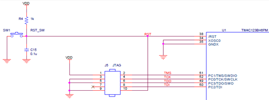
The schematic is the picture below. (file : 7457.Tiva schematic.pdf)
Some example codes such as LED blinking worked perfectly. However, while using
sometimes error pop-up. The following error is this.
CORTEX_M4_0: JTAG Communication Error: (Error -1170 @ 0x0) Unable to access the DAP. Reset the device, and retry the operation. If error persists, confirm configuration, power-cycle the board, and/or try more reliable JTAG settings (e.g. lower TCLK). (Emulation package 5.1.450.0)
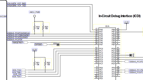
Comparing my circuit and the EK-TM4C123GXL 's schematic, I think I need to insert the pull-up resistors.
(schematic of EK-TM4C123GXL page 22, 5822.EK-TM4C123GXL LaunchPad(LM4F120).pdf)
However, there was something confusing.
At ARM Information site, the descriptions of the pull-up and pull-down settings aredifferent.
(link : http://infocenter.arm.com/help/index.jsp?topic=/com.arm.doc.dui0517b/Cjaeccji.html )
The EK-TM4C123GXL schematic shows that the pull-up resistor is required at the TCK and TMS pins.
On the other hand, the ARM info web says that TMS, TDI, TDO must have pull-ups
and TCK must have pull-down.
- The question is -
1. Placing a Pull-up/down resistor to the JTAG pins are mandatory?
(Some codes have been downloaded sucessfully without the resistors...)
2. If the resistors are needed should the TCK pin needs a pull-up or pull-down?
3. When does this error [CORTEX_M4_0: JTAG Communication Error: Error -1170] occur?
4. The pull-up resistor 1K Ohm at reset switch, does this resistor have to change to 10k Ohm?
Regards, Min-Ku


