This thread has been locked.

If you have a related question, please click the "Ask a related question" button in the top right corner. The newly created question will be automatically linked to this question.

Connecting Stellaris Launchpad with 16x2 LCD

Hello, I am new to the Ti Cortex-M4. I am using the Stellaris launchpad. I am trying to connect my Stellaris Launchpad with my LCD. I want to interface with my LCD by using 8-Bit Data interfacing. I am having trouble doing that. I have chosen PORTA and PORTB to connect to the LCD data pins. I have grounded the Read/Write Pin so its always a write to the memory of the LCD. I connected PE1 to the Register Select  Pin (RS) and PE2 to the Enable Pin (E).  Below you will find my pin connections from the Stellaris Launchpad to the LCD.

Stellaris Launchpad Pin PB0 PB1 PA2 PA3 PA4 PA5 PA6 PA7
LCD Pins 7 (D0) 8 (D1) 9 (D2) 10 (D3) 11 (D4) 12 (D5) 13 (D6) 14 (D7)

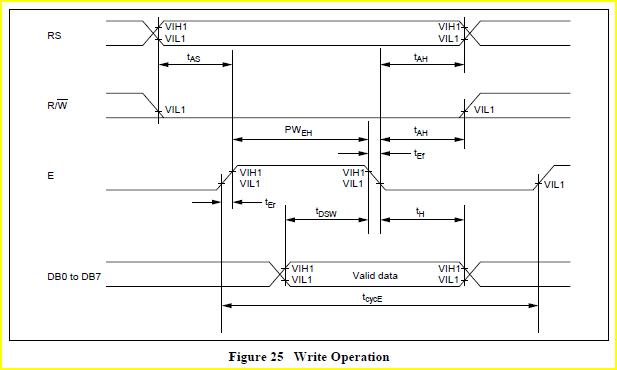
Now to initialize the LCD I must send these Commands 0x38, 0x0E, 0x01 and Send a HIGH to LOW to the Enable Pin and The RS Pin is 0. Below you will find my code


#include "inc/hw_types.h"
#include "inc/hw_memmap.h"
#include "driverlib/sysctl.h"
#include "driverlib/gpio.h"
#include "stdio.h"

int main(void)
{
SysCtlClockSet(SYSCTL_SYSDIV_4|SYSCTL_USE_PLL|SYSCTL_XTAL_16MHZ|
SYSCTL_OSC_MAIN);

SysCtlPeripheralEnable(SYSCTL_PERIPH2_GPIOA);
SysCtlPeripheralEnable(SYSCTL_PERIPH2_GPIOB);
SysCtlPeripheralEnable(SYSCTL_PERIPH2_GPIOE);

GPIOPinTypeGPIOOutput(GPIO_PORTA_BASE , GPIO_PIN_2 | GPIO_PIN_3 | GPIO_PIN_4 | GPIO_PIN_5 | GPIO_PIN_6 |
GPIO_PIN_7);
GPIOPinTypeGPIOOutput(GPIO_PORTB_BASE, GPIO_PIN_0 | GPIO_PIN_1);
GPIOPinTypeGPIOOutput(GPIO_PORTE_BASE, GPIO_PIN_1 | GPIO_PIN_2);

SysCtlDelay(1000000);

//--------------- First Command 2 Lines and 5x7 Matrix (D0-D7, 8bit)----------------//

// RS = 0, E = 0
GPIOPinWrite(GPIO_PORTE_BASE, GPIO_PIN_1 | GPIO_PIN_2, 0x00);

// PORTA = 56 (DEC), 0x38 (HEX)
GPIOPinWrite(GPIO_PORTA_BASE , GPIO_PIN_2 | GPIO_PIN_3 | GPIO_PIN_4 | GPIO_PIN_5 | GPIO_PIN_6 |
GPIO_PIN_7, 0x38);
// PORTB = 0 (DEC), 0x00 (HEX)
GPIOPinWrite(GPIO_PORTB_BASE, GPIO_PIN_0 | GPIO_PIN_1, 0x00);

// Latch Enable HIGH-to-LOW PULSE
GPIOPinWrite(GPIO_PORTE_BASE, GPIO_PIN_1 | GPIO_PIN_2, 0x04);
GPIOPinWrite(GPIO_PORTE_BASE, GPIO_PIN_1 | GPIO_PIN_2, 0x00);

SysCtlDelay(100000);

//-------------------------------END OF First Command------------------------------//

//--------------- Second Command Display on, cursor blinking ----------------//

// RS = 0, E = 0
GPIOPinWrite(GPIO_PORTE_BASE, GPIO_PIN_1 | GPIO_PIN_2, 0x00);

// PORTA = 12 (DEC), 0x0C (HEX)
GPIOPinWrite(GPIO_PORTA_BASE , GPIO_PIN_2 | GPIO_PIN_3 | GPIO_PIN_4 | GPIO_PIN_5 | GPIO_PIN_6 |
GPIO_PIN_7, 0x0C);
// PORTB = 2 (DEC), 0x02 (HEX)
GPIOPinWrite(GPIO_PORTB_BASE, GPIO_PIN_0 | GPIO_PIN_1, 0x02);

// Latch Enable HIGH-to-LOW PULSE
GPIOPinWrite(GPIO_PORTE_BASE, GPIO_PIN_1 | GPIO_PIN_2, 0x04);
GPIOPinWrite(GPIO_PORTE_BASE, GPIO_PIN_1 | GPIO_PIN_2, 0x00);

SysCtlDelay(100000);

//-------------------------------END OF Second Command------------------------------//

//--------------- Third Command Clear Screen ----------------//

// RS = 0, E = 0
GPIOPinWrite(GPIO_PORTE_BASE, GPIO_PIN_1 | GPIO_PIN_2, 0x00);

// PORTA = 0 (DEC), 0x00 (HEX)
GPIOPinWrite(GPIO_PORTA_BASE , GPIO_PIN_2 | GPIO_PIN_3 | GPIO_PIN_4 | GPIO_PIN_5 | GPIO_PIN_6 |
GPIO_PIN_7, 0x00);
// PORTB = 1 (DEC), 0x01 (HEX)
GPIOPinWrite(GPIO_PORTB_BASE, GPIO_PIN_0 | GPIO_PIN_1, 0x01);

// Latch Enable HIGH-to-LOW PULSE
GPIOPinWrite(GPIO_PORTE_BASE, GPIO_PIN_1 | GPIO_PIN_2, 0x04);
GPIOPinWrite(GPIO_PORTE_BASE, GPIO_PIN_1 | GPIO_PIN_2, 0x00);

SysCtlDelay(2000000);

//-------------------------------END OF Third Command------------------------------//


while(1)
{

}
}

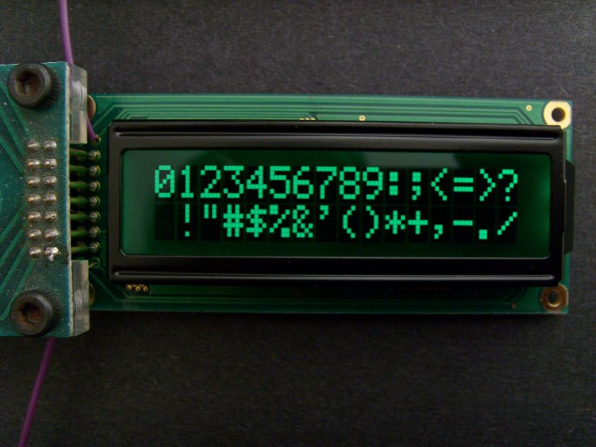
After I program the Stellaris Launchpad nothing happens to the LCD it doesn't get cleared. I have checked my pin connections of my Stellaris Launchpad to the LCD and  they are correct. Do you have any suggestions on how to make my code work.

Thank You

  • Mahmoud Abdel-Rahman said:
    nothing happens to the LCD it doesn't get cleared.

    "Nothing happens" - very close to famed/beloved, "does not work" - far more detail required.  How do you know it was not cleared? 

    Suspect much of your effort springs from my post/data contributions- C2000 area.  Do you see the pixel field?  Have you installed a contrast pot - and fed its wiper to the Vo pin of the Lcd?

    You add "great" complexity by "mixing" Ports B & A to serve as "data bus."  W/out full study of your code - cannot comment if you've done this correctly - but my belief is that complexity should be avoided until the basics are achieved.  (i.e. Lcd up/running)  Realize you want "usual suspects" PA0/PA1 for UART - but that should happen later - not now!

    There is a less demanding GPIO scheme - employs just 4 Data Bits + 2 Control Bits - but far more complex - time & again we've seen clients fail/frustrate - thus the 8 Data Bit method you've adopted is far safer - easier and faster.  (2x+ transfer rate of 4 bit method)  Four bit mode also is extremely susceptible to noise/glitch - if one transmission is impacted - Lcd becomes disordered - must be reset (sometimes de-powered) to recover.  IMHO (a 20+ year considered one - in this case) avoid 4 bit mode until 8 bit mode is mastered - and you can insure a "noise reduced" operatiing environment...  (bit hard - that...)

    As the timing charts I past presented "http://e2e.ti.com/support/microcontrollers/c2000/f/171/p/210923/955141.aspx#955141" reveal:

    you must present data & RS first - with E held low.  Then - after E's hold time is met - you drive E high - maintaining data & RS stable @ original levels.  It's likely that you'll need some delay to insure that E's hold time is met.  And your code shows none!  Look here:

    // RS = 0, E = 0
    GPIOPinWrite(GPIO_PORTE_BASE, GPIO_PIN_1 | GPIO_PIN_2, 0x00);// PORTA = 56 (DEC), 0x38 (HEX)
    GPIOPinWrite(GPIO_PORTA_BASE , GPIO_PIN_2 | GPIO_PIN_3 | GPIO_PIN_4 | GPIO_PIN_5 | GPIO_PIN_6 | GPIO_PIN_7, 0x38);
    // PORTB = 0 (DEC), 0x00 (HEX)
    GPIOPinWrite(GPIO_PORTB_BASE, GPIO_PIN_0 | GPIO_PIN_1, 0x00);

    // Latch Enable HIGH-to-LOW PULSE
    GPIOPinWrite(GPIO_PORTE_BASE, GPIO_PIN_1 | GPIO_PIN_2, 0x04); 

    GPIOPinWrite(GPIO_PORTE_BASE, GPIO_PIN_1 | GPIO_PIN_2, 0x00);  // Error!  E pulse may not meet PWEH (230nS)

    This construct must extend each/every time you "invoke" an E write. 

    Note further - when you order E "low" - code shown impacts RS - too!  (of no consequence while in Command Mode (RS=0) but "deadly" when in Data Mode (RS=1).  E must toggle independently of all other bits - thus your code for E (rise or fall) must "strip out" any modification to RS....

    Suggest that you change the init to: 38, 38, 06, 0E, 01 - and provide 1mS delay between each. 

    Suspect that you'll prove resistant to temporary change to more normal/customary dedication of single port to data bus.  While you may succeed w/brief init via "mixed port" construct - real world data "massaging" - for each/every char - beyond my time/comfort...  And - when you transact w/Port A UART - unless careful - you'll "spoil" data also resident Port A - destined for the Lcd.  (as Lcd data may "impinge" upon UART - extra care needed!)

    Again - as related post notes - once your init is executed - adjust contrast pot so that dot field is just visible.  (cursor should be in play - Row 1, Char 1) 

    Should this not occur - while you report "checking" connections - suggest a scope or DVM probe - @ the Lcd header - with a static D-Bus of (0xAA first - followed by 0x55) and w/ static C-Bus of (0x04 first, followed by 0x02.)  These codes are "poor man's" walking "0" - will confirm connections' completeness and possible, adjacent pin shorts. 

    Suspect others may be interested - will provide key spec for "grandfather" of all Lcd Text Controllers - next post.  Update: completed, below...

    Bon chance, mon ami...

  • Key Specs/Timing for HD44780 Text Lcd Controller.  Please credit Hitachi.   (certain fields may be eased somewhat - newer controllers)

    Note: especially critical that timings: TAS (40nS), PWEH (230nS), TDSW (80nS), TAH & TH (10nS) be in compliance.  Common toggling of RS & E will violate!  {cb1}

    Read is not required.  (RW may tie to ground)  Read proves useful to minimize inter-character delays (via busy bit - D7) & when a display "dump" proves useful.  {cb1}

  • Hello, Thank you for your help. The reason I am not using a single port is that because the Stellaris Launchpad doesn't have a complete single port on the in/out pins provided by the board (Ex. PA2, PA3, PA4, PA5, PA6, PA7, but it doesn't have PA0 and PA1) this is why I am using 3 ports to interface with my LCD. Sorry if I wasn't clear earlier on what was happening with my LCD when I download the program on the Stellaris Launchpad. When I connect the 5V and the GND to the LCD, all the pixels of the matrices of the first pixels gets doted and the second row is empty nothing is doted in the matrices in it. When I program the Stellaris Launchpad both the matrices of the rows of the LCD gets doted. As you suggested it is a timing problem, I think that it is a timing problem too. Thank you for your replay and for the diagrams. I will try your suggestions and I will notify you with what happened. Thanks

  • Thank you - appreciate your comment.  Suspect that your E pulse is too narrow.  (while spec lists 230nS - earlier controllers required up to 450nS)  And - your code to drive E "high to low" - impacts RS as well. (Bad!)

    You must correct each.

    These controllers default into single row mode - upon correct initialization (as shown) the 2nd row's pixel field will properly reveal.  (mere ghost - prior)

    Older displays often required a slighly negative voltage on Vo - newer ones usually work ~0.5V.  (positive)  Pot will be big help.

    Fix the E width (i.e. insert delay after setting E (alone) high and make any/all E "handling" unique to E.  (We do that via unique set-ups for Command (RS=0) vs. Data (RS=1) Writes)

    With RS=0 - Home position top row results from 0x80 or 0x02.  Home, bottom row from 0xC0.  (0xC8 yields 9th position - bottom row)  0x01 clears the display.

    You must provide ~40uS delay after every char write - and perhaps 2mS after 0x01/0x02.  Should your display show gaps - violation of display's "busy time" - usual suspect...  Suggest larger delays between each/every of the init. codes.  (and - 38, 38, 06, 0E, 01 All w/RS=0) far better for Gov't work...)

    To encourage your/others interest/persistence - below shines, "light from data-tunnel's end..."

    (early (unretouched) photo of one of our firm's Hi-Contrast, Extended Viewing Angle Text Lcd - accepts UART, I2C, SPI, CAN & up to 4x5 key matrix...)  Note Spring-loaded "data clip" massaged into use as "no solder/quick on/off" Test Clip...

  • Continuing further - this series, "tease out an 8 bit port from lunchlaunchpad."

    Kindly see this new (broader) post which further (perhaps better) details:

    http://e2e.ti.com/support/microcontrollers/tiva_arm/f/908/t/279242.aspx

  • Hello cb1, I have reconfigured the connections to my LCD. In the table below you will find my new configurations

    Stellaris Launchpad PB0 PB1 PB2 PB3 PB4 PB5 PB6 PB7 PA6 PA7
    LCD Pins 7(D0) 8(D1) 9(D2) 10(D3) 11(D4) 12(D5) 13(D6) 14(D7) 4(RS) 6(E)

    The other LCD Pins, I have connected the VSS to the Ground Pin1, VCC to the 5V Supply Pin2, VEE Power Supply to control contrast to the Ground Pin 3 and the R/W to the Ground Pin5.

    in the function SysCtlClockSet(SYSCTL_DIV_16 | SYSCTL_USE_PLL | SYSCTL_XTAL_16MHZ | SYSCTL_OSC_MAIN) if my assumptions are correct, then I have divided the PLL Clock Generator by 16 which will give me 12.5 MHZ. I used the following equation to calculate my nanoseconds, milliseconds, microseconds, and seconds

    delay = DelayTimeInSeconds((1/12500000)*3). 

    I have found out that PORTB is a complete port unlike the other PORTS. I have modified my code as you suggested. Below you will find the code

    #include "inc/hw_types.h"
    #include "inc/hw_memmap.h"
    #include "driverlib/sysctl.h"
    #include "driverlib/gpio.h"
    #include "stdio.h"

    int main(void)
    {
    //------------------- Stellaris Launchpad System Initilization------------------//
    SysCtlClockSet(SYSCTL_SYSDIV_16 | SYSCTL_USE_PLL| SYSCTL_XTAL_16MHZ|
    SYSCTL_OSC_MAIN);

    SysCtlPeripheralEnable(SYSCTL_PERIPH_GPIOA);
    SysCtlPeripheralEnable(SYSCTL_PERIPH_GPIOB);

    GPIOPinTypeGPIOOutput(GPIO_PORTA_BASE, GPIO_PIN_6 | GPIO_PIN_7);
    GPIOPinTypeGPIOOutput(GPIO_PORTB_BASE, GPIO_PIN_0 | GPIO_PIN_1| GPIO_PIN_2 | GPIO_PIN_3
    |GPIO_PIN_4 | GPIO_PIN_5| GPIO_PIN_6 | GPIO_PIN_7);

    //------------------End of Stellaris Launchpad System Initilization------------//

    //Wait 15 Miliseconds after LCD Power Up//
    SysCtlDelay(62500);

    GPIOPinWrite(GPIO_PORTA_BASE, GPIO_PIN_6 | GPIO_PIN_7, 0x00);

    //-------------------------------First LCD Command----------------------------//

    //Put on the Data Pins 0x38 to get 2 Lines 5x7 Matrix (D0-D7, 8Bit)//
    GPIOPinWrite(GPIO_PORTB_BASE, GPIO_PIN_0 | GPIO_PIN_1| GPIO_PIN_2 | GPIO_PIN_3
    |GPIO_PIN_4 | GPIO_PIN_5| GPIO_PIN_6 | GPIO_PIN_7, 0x38);

    //Register Select(RS) = 0, Enable(E) = 1//
    GPIOPinWrite(GPIO_PORTA_BASE, GPIO_PIN_6 | GPIO_PIN_7, 0x80);

    //Enable Pulse Width (High Level) 230 nano second//
    SysCtlDelay(2);

    //Register Select(RS) = 0, Enable(E) = 0//
    GPIOPinWrite(GPIO_PORTA_BASE, GPIO_PIN_6 | GPIO_PIN_7, 0x00);
    //---------------------------End of First LCD Command------------------------//

    //1 milliseconds delay//
    SysCtlDelay(4167);

    //-------------------------------Second LCD Command----------------------------//

    //Put on the Data Pins 0x38 to get 2 Lines 5x7 Matrix (D0-D7, 8Bit)//
    GPIOPinWrite(GPIO_PORTB_BASE, GPIO_PIN_0 | GPIO_PIN_1| GPIO_PIN_2 | GPIO_PIN_3
    |GPIO_PIN_4 | GPIO_PIN_5| GPIO_PIN_6 | GPIO_PIN_7, 0x38);

    //Register Select(RS) = 0, Enable(E) = 1//
    GPIOPinWrite(GPIO_PORTA_BASE, GPIO_PIN_6 | GPIO_PIN_7, 0x80);

    //Enable Pulse Width (High Level) 230 nano second//
    SysCtlDelay(2);

    //Register Select(RS) = 0, Enable(E) = 0//
    GPIOPinWrite(GPIO_PORTA_BASE, GPIO_PIN_6 | GPIO_PIN_7, 0x00);
    //---------------------------End of Second LCD Command------------------------//

    //1 milliseconds delay//
    SysCtlDelay(4167);

    //-------------------------------Third LCD Command----------------------------//

    //Put on the Data Pins 0x38 to get 2 Lines 5x7 Matrix (D0-D7, 8Bit)//
    GPIOPinWrite(GPIO_PORTB_BASE, GPIO_PIN_0 | GPIO_PIN_1| GPIO_PIN_2 | GPIO_PIN_3
    |GPIO_PIN_4 | GPIO_PIN_5| GPIO_PIN_6 | GPIO_PIN_7, 0x06);

    //Register Select(RS) = 0, Enable(E) = 1//
    GPIOPinWrite(GPIO_PORTA_BASE, GPIO_PIN_6 | GPIO_PIN_7, 0x80);

    //Enable Pulse Width (High Level) 230 nanosecond//
    SysCtlDelay(2);

    //Register Select(RS) = 0, Enable(E) = 0//
    GPIOPinWrite(GPIO_PORTA_BASE, GPIO_PIN_6 | GPIO_PIN_7, 0x00);
    //---------------------------End of Third LCD Command------------------------//

    //1 milliseconds delay//
    SysCtlDelay(4167);

    //-------------------------------Fourth LCD Command----------------------------//

    //Put on the Data Pins 0x0E Command to get Display ON, Cursor Blinking//
    GPIOPinWrite(GPIO_PORTB_BASE, GPIO_PIN_0 | GPIO_PIN_1| GPIO_PIN_2 | GPIO_PIN_3
    |GPIO_PIN_4 | GPIO_PIN_5| GPIO_PIN_6 | GPIO_PIN_7, 0x0E);

    //Register Select(RS) = 0, Enable(E) = 1//
    GPIOPinWrite(GPIO_PORTA_BASE, GPIO_PIN_6 | GPIO_PIN_7, 0x80);

    //Enable Pulse Width (High Level) 1 microsecond//
    SysCtlDelay(2);

    //Register Select(RS) = 0, Enable(E) = 0//
    GPIOPinWrite(GPIO_PORTA_BASE, GPIO_PIN_6 | GPIO_PIN_7, 0x00);
    //---------------------------End of Fourth LCD Command------------------------//

    // 1 millisecond delay
    SysCtlDelay(4167);

    //-------------------------------Fifth LCD Command----------------------------//

    //Put on the Data Pins 0x01 command to Clear the LCD Screen//
    GPIOPinWrite(GPIO_PORTB_BASE, GPIO_PIN_0 | GPIO_PIN_1| GPIO_PIN_2 | GPIO_PIN_3
    |GPIO_PIN_4 | GPIO_PIN_5| GPIO_PIN_6 | GPIO_PIN_7, 0x01);

    //Register Select(RS) = 0, Enable(E) = 1//
    GPIOPinWrite(GPIO_PORTA_BASE, GPIO_PIN_6 | GPIO_PIN_7, 0x80);

    //Enable Pulse Width (High Level) 1 microsecond//
    SysCtlDelay(2);

    //Register Select(RS) = 0, Enable(E) = 0//
    GPIOPinWrite(GPIO_PORTA_BASE, GPIO_PIN_6 | GPIO_PIN_7, 0x00);

    //Delay 2ms after the 0x01 and 0x02//
    SysCtlDelay(8333);
    //---------------------------End of Fifth LCD Command------------------------//

    //1 Millisecond Delay//
    SysCtlDelay(4167);

    while(1)
    {

    }
    }

    I am still have problems getting my LCD to work. When I first connect the power to the LCD, all the matrices of the first row of the LCD gets dotted. When I upload the program to the Stellaris Launchpad and Run it the matrices of the first and second rows of the LCD gets dotted. Any suggestions on what is wrong.

    Thank You.

  • You've surely made great effort - sorry victory not yet at hand.

    Your code is nicely detailed - and after quick (but caring) scan - I find nothing wrong.

    So - timing is always concern #1 and connection of proper voltage to Vo is concern #2.  Past suggested that you employ contrast pot - set to ~0.5V.  Have you done this?  As for timing - very often the compiler will eliminate delays - although I don't know if that holds for your compiler - and SysCtlDelay().  If you can confirm the width of "E" via a scope - that would be helpful.  In the absence of scope - connect an Led - and confirm that (substantially longer) delay works w/that.

    Realize further that code you've presented (past & today) has initialized the Lcd - but not provided character data.  (yet)  Thus - it is possible that all is well - the visibility of row 2"s pixel field - post initialization - is a good sign.

    Data Writes - as opposed to commands - requires that RS = 1 - yet the E strobe mechanism remains the same.  Here's an example - in your format:

    //Register Select(RS) = 1, Enable(E) = 1//
    GPIOPinWrite(GPIO_PORTA_BASE, GPIO_PIN_6 | GPIO_PIN_7, 0xC0);  // both pins: 6 & 7 high

    //Enable Pulse Width (High Level) 1 microsecond//
    SysCtlDelay(2);

    //Register Select(RS) = 1, Enable(E) = 0//
    GPIOPinWrite(GPIO_PORTA_BASE, GPIO_PIN_6 | GPIO_PIN_7, 0x40);  // pin 6 remains high, pin 7 falls

    Here's a simplification - (direct carpal tunnel prevention/savings to charity)

    earlier in your program declare unsigned char bus_8;

    bus_8 =  (GPIO_PIN_0 | GPIO_PIN_1 | GPIO_PIN_2 | GPIO_PIN_3 | GPIO_PIN_4 | GPIO_PIN_5 | GPIO_PIN_6 | GPIO_PIN_7);  // = 0xFF

    //Put "A" upon the Data Bus "0x41" //
    GPIOPinWrite(GPIO_PORTB_BASE,  bus_8 , 0x41);  // depending upon your compiler - "A" may work as well (param 3) and 0xFF may serve as (param 2).

    Again - it may be that you are, "good to go" - and that absence of display data becalms your quiet screen.  Listings herein guide...

    Again - should this not bring your display to life - I'd confirm the width of your E pulse.  If good - suggest that you output walking "1s" & "0s" - as past described.  Be sure to check for these @ the Lcd header - not just the MCU board.  Look for bad solder joints, possibly shorts - each/every Lcd pin.

     Update: (12:30 CST) just noted that you describe pin 3 (Vo) as ground.  Depending upon the Lcd - that may render the pixel field too dark.  (I know many do this - but they've not designed/sold 100K+ - use of a pot aids considerably - prevents waste...time/effort...)

  • Hello cb1, the LCD has finally worked. I took your advice and wrote a character on the LCD and it appeared. The pixel field was too dark, I connected the LCD back lights and the character appeared and I was able to see it. I will connect a pot to the LCD to brighten the pixel fields. Thank you for your help.

  • Good for you my friend - you worked hard & systematically - deserve congratulations.

    Should you use a 10K pot - suggest that you place a 10K or so additional resistor in series with 3V3 - and feed that to one end of the pot.  Tie the other pot end to ground - pot's wiper then feeds Vo (pin 3) your Lcd.  The added resistor will serve to better center your pot - when adjusting contrast.  (without that R - pot will be very far to one end)

    Be sure to include proper current limiting when driving any Led backlight. 

  • Can you show me your code

  • Hello Ngo Nguyen. Sorry that I am replying late. Below you will find the code for the LCD

    #include "inc/hw_types.h"
    #include "inc/hw_memmap.h"
    #include "driverlib/sysctl.h"
    #include "driverlib/gpio.h"
    #include "stdio.h"

    int main(void)
    {
    //------------------- Stellaris Launchpad System Initilization------------------//
    SysCtlClockSet(SYSCTL_SYSDIV_16 | SYSCTL_USE_PLL| SYSCTL_XTAL_16MHZ|
    SYSCTL_OSC_MAIN);

    SysCtlPeripheralEnable(SYSCTL_PERIPH_GPIOA);
    SysCtlPeripheralEnable(SYSCTL_PERIPH_GPIOB);

    GPIOPinTypeGPIOOutput(GPIO_PORTA_BASE, GPIO_PIN_6 | GPIO_PIN_7);
    GPIOPinTypeGPIOOutput(GPIO_PORTB_BASE, GPIO_PIN_0 | GPIO_PIN_1| GPIO_PIN_2 | GPIO_PIN_3
    |GPIO_PIN_4 | GPIO_PIN_5| GPIO_PIN_6 | GPIO_PIN_7);

    //------------------End of Stellaris Launchpad System Initilization------------//

    //Wait 15 Miliseconds after LCD Power Up//
    SysCtlDelay(62500);

    GPIOPinWrite(GPIO_PORTA_BASE, GPIO_PIN_6 | GPIO_PIN_7, 0x00);

    //-------------------------------First LCD Command----------------------------//

    //Put on the Data Pins 0x38 to get 2 Lines 5x7 Matrix (D0-D7, 8Bit)//
    GPIOPinWrite(GPIO_PORTB_BASE, GPIO_PIN_0 | GPIO_PIN_1| GPIO_PIN_2 | GPIO_PIN_3
    |GPIO_PIN_4 | GPIO_PIN_5| GPIO_PIN_6 | GPIO_PIN_7, 0x38);

    //Register Select(RS) = 0, Enable(E) = 1//
    GPIOPinWrite(GPIO_PORTA_BASE, GPIO_PIN_6 | GPIO_PIN_7, 0x80);

    //Enable Pulse Width (High Level) 230 nano second//
    SysCtlDelay(2);

    //Register Select(RS) = 0, Enable(E) = 0//
    GPIOPinWrite(GPIO_PORTA_BASE, GPIO_PIN_6 | GPIO_PIN_7, 0x00);
    //---------------------------End of First LCD Command------------------------//

    //1 milliseconds delay//
    SysCtlDelay(4167);

    //-------------------------------Second LCD Command----------------------------//

    //Put on the Data Pins 0x38 to get 2 Lines 5x7 Matrix (D0-D7, 8Bit)//
    GPIOPinWrite(GPIO_PORTB_BASE, GPIO_PIN_0 | GPIO_PIN_1| GPIO_PIN_2 | GPIO_PIN_3
    |GPIO_PIN_4 | GPIO_PIN_5| GPIO_PIN_6 | GPIO_PIN_7, 0x38);

    //Register Select(RS) = 0, Enable(E) = 1//
    GPIOPinWrite(GPIO_PORTA_BASE, GPIO_PIN_6 | GPIO_PIN_7, 0x80);

    //Enable Pulse Width (High Level) 230 nano second//
    SysCtlDelay(2);

    //Register Select(RS) = 0, Enable(E) = 0//
    GPIOPinWrite(GPIO_PORTA_BASE, GPIO_PIN_6 | GPIO_PIN_7, 0x00);
    //---------------------------End of Second LCD Command------------------------//

    //1 milliseconds delay//
    SysCtlDelay(4167);

    //-------------------------------Third LCD Command----------------------------//

    //Put on the Data Pins 0x38 to get 2 Lines 5x7 Matrix (D0-D7, 8Bit)//
    GPIOPinWrite(GPIO_PORTB_BASE, GPIO_PIN_0 | GPIO_PIN_1| GPIO_PIN_2 | GPIO_PIN_3
    |GPIO_PIN_4 | GPIO_PIN_5| GPIO_PIN_6 | GPIO_PIN_7, 0x06);

    //Register Select(RS) = 0, Enable(E) = 1//
    GPIOPinWrite(GPIO_PORTA_BASE, GPIO_PIN_6 | GPIO_PIN_7, 0x80);

    //Enable Pulse Width (High Level) 230 nanosecond//
    SysCtlDelay(2);

    //Register Select(RS) = 0, Enable(E) = 0//
    GPIOPinWrite(GPIO_PORTA_BASE, GPIO_PIN_6 | GPIO_PIN_7, 0x00);
    //---------------------------End of Third LCD Command------------------------//

    //1 milliseconds delay//
    SysCtlDelay(4167);

    //-------------------------------Fourth LCD Command----------------------------//

    //Put on the Data Pins 0x0E Command to get Display ON, Cursor Blinking//
    GPIOPinWrite(GPIO_PORTB_BASE, GPIO_PIN_0 | GPIO_PIN_1| GPIO_PIN_2 | GPIO_PIN_3
    |GPIO_PIN_4 | GPIO_PIN_5| GPIO_PIN_6 | GPIO_PIN_7, 0x0E);

    //Register Select(RS) = 0, Enable(E) = 1//
    GPIOPinWrite(GPIO_PORTA_BASE, GPIO_PIN_6 | GPIO_PIN_7, 0x80);

    //Enable Pulse Width (High Level) 1 microsecond//
    SysCtlDelay(2);

    //Register Select(RS) = 0, Enable(E) = 0//
    GPIOPinWrite(GPIO_PORTA_BASE, GPIO_PIN_6 | GPIO_PIN_7, 0x00);
    //---------------------------End of Fourth LCD Command------------------------//

    // 1 millisecond delay
    SysCtlDelay(4167);

    //-------------------------------Fifth LCD Command----------------------------//

    //Put on the Data Pins 0x01 command to Clear the LCD Screen//
    GPIOPinWrite(GPIO_PORTB_BASE, GPIO_PIN_0 | GPIO_PIN_1| GPIO_PIN_2 | GPIO_PIN_3
    |GPIO_PIN_4 | GPIO_PIN_5| GPIO_PIN_6 | GPIO_PIN_7, 0x01);

    //Register Select(RS) = 0, Enable(E) = 1//
    GPIOPinWrite(GPIO_PORTA_BASE, GPIO_PIN_6 | GPIO_PIN_7, 0x80);

    //Enable Pulse Width (High Level) 1 microsecond//
    SysCtlDelay(2);

    //Register Select(RS) = 0, Enable(E) = 0//
    GPIOPinWrite(GPIO_PORTA_BASE, GPIO_PIN_6 | GPIO_PIN_7, 0x00);

    //Delay 2ms after the 0x01 and 0x02//
    SysCtlDelay(8333);
    //---------------------------End of Fifth LCD Command------------------------//

    //1 Millisecond Delay//
    SysCtlDelay(4167);

    //--------------------------- First LCD Data Write--------------------------//
    GPIOPinWrite(GPIO_PORTB_BASE, GPIO_PIN_0 | GPIO_PIN_1| GPIO_PIN_2 | GPIO_PIN_3
    |GPIO_PIN_4 | GPIO_PIN_5| GPIO_PIN_6 | GPIO_PIN_7, 0x42);

    //Register Select(RS) = 1, Enable(E) = 1//
    GPIOPinWrite(GPIO_PORTA_BASE, GPIO_PIN_6 | GPIO_PIN_7, 0xC0);

    //Enable Pulse Width (High Level) 1 microsecond//
    SysCtlDelay(2);

    //Register Select(RS) = 1, Enable(E) = 0//
    GPIOPinWrite(GPIO_PORTA_BASE, GPIO_PIN_6 | GPIO_PIN_7, 0x40);

    //Delay 2ms after the 0x01 and 0x02//
    SysCtlDelay(8333);
    //--------------------------- End of LCD Data Write-------------------------//

    while(1)
    {

    }
    }

    After applying that code you should be able to write on your LCD. If you need any more help reply back.

  • As an early contributor to this thread - am concerned that this code:

    //Register Select(RS) = 1, Enable(E) = 1//
    GPIOPinWrite(GPIO_PORTA_BASE, GPIO_PIN_6 | GPIO_PIN_7, 0xC0);

    impacts both RS & E simultaneously.  Can't recall if I placed the HD44780 (copied by most clones) timing chart here - but there was an advisory to "not" drive both RS & E simultaneously.  Now it may be that this restriction "only applies" upon the "fall" of enable - it's been quite awhile since I've checked the spec.

    Also fear that "SysCtlDelay(2);" which shoots for ~230nS delay may be too short.  (i.e. larger value would be safer)

    Beware also that different MCU System Clocks will impact any/all delays which are so based.  (i.e. SysCtlDelay(x);)

    And - Mahmoud great that you took the reins on this one - true spirit of the forum...

  • Hi,

    I tried to run this code but it shows an error

     error:  #5: cannot open source input file "inc/hw_types.h": No such file or directory

    please tell me what to do?

  • Hi Arish,

         Do you have hw_types.h at the inc folder location?

         Also, it would be better to just create a new post regarding your question.

    -kel

  • Hi Mahmoud,

    I tried using my 16x2 LCD with your code.. but my display shows all the matrices of the first and second row as dotted.. I have also used a POT and have turned ON the backlight..

    I have configured the system clock to 40MHz and have used a delay of 1us for the enable signal.. The LCD is 1602ZFA..

    Any suggestions??

  • Hi Vikas,

    About your problem first check your hardware connection. When I did that project I used PortB because it was the only port that started from PB0 to PB7. Check your connection of the POT with the LCD that you have connected it to the correct pins. Next the software, when I wrote that code I used the DEFAULT value of the SYSTEM CLOCK "SysCtlClockSet(SYSCTL_SYSDIV_4|SYSCTL_USE_PLL|SYSCTL_XTAL_16MHZ| SYSCTL_OSC_MAIN);" and you configured your clock to 40MHz, so when you use the code please use the default values of everything. Also please check the previous replys of the same post you will find a diagram explaining the timing for the RS, R/W, EN pins that are required during the Read or Write Operations. For the delay after each operation "SysCtlDelay(4167);" the integer parameter in the SysCtlDelay() function I have calculated based on the DEFAULT configurations. When you have 2 rows that are dotted that means you have problems with the delays between every command you send to the LCD. I hope this helps.

  • @ Mahmoud,

    Greetings - and how welcome to see you - after earlier requesting guidance - now offering the same in return!  And with care & skill - I'd say...

    Truly the spirit of the forum - requester needs to "dig a bit." (just as you did so persistently - and so well - to a successful outcome)

  • Have you ever write code conect Tiva kit. 

  • Hi Mohmoud, May i know the output displayed in lcd for this code?
  • Hello Tran Hieu,

    I don't have a TivaC Kit. I have the Stellaris Launchpad LM4F120XL. I wrote it for the Stellaris. I think it would be the same code. Also the code I wrote I used the Stellarisware API. I will post another code in a few days for the use of the LCD. Sorry for the late reply I just have been busy with other stuff.

    Thank You

  • Hello M.Mary Babitha,

    Sorry for the late reply. I am sorry I didn't save the code I wrote, but I will write it again and post it in a couple of days. I will write the new code only using the Stellarisware API in the delay function, the rest of the code I will not use the API.

    Thank You,
    Mahmoud