This thread has been locked.

If you have a related question, please click the "Ask a related question" button in the top right corner. The newly created question will be automatically linked to this question.

Drive delta connection BLDC

Dear sir

I use the same driver to drive Y connection BLDC and delta connection BLDC

The Y connection is spin normally , but delta connection BLDC is fail

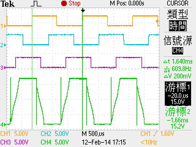
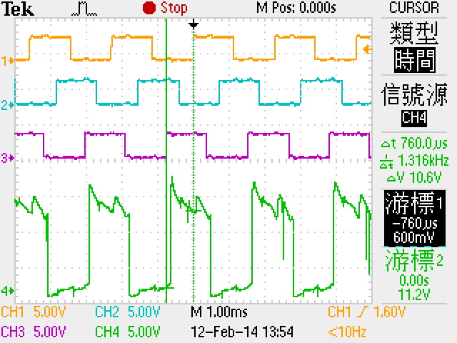
And this is the waveform below

CH1:HS1  CH2:HS2  CH3:HS3  CH4: U PHASE

Could anybody give a tip for drive the delta connection BLDC 

Thanks. 

  • Hi Hong-yao

    What is your driver? is it sensored trapezoidal control?

    Have you pay attention to the hall sensor and U, V, W connection sequences when changing the motor?

    Thanks.

  • Wilson

    Yes,my driver is sensored trapezoidal control

    I think this is correct about hall sensor and U,V,W connection

    because it's spinning normally  on CW condition

    It's only fail on CCW condition.

  • Hi Hong-yao

    It is possible that even in the false U, V, W connection sequence, the driver still turns the motor running in one direction.

    Also in one-phase-missing condition, there is also possible for the motor running in one direction but stalled in the other direction.

    I would still recommended a hardware connection checking and sequence enumeration test.

    Beside, for the same coils, delta connection may leads to more startup current and other motor parameters changing. Please make should your driver is still capable to adapt the motor parameters changing.

    Thanks.

  • Hi Wilson

    Thank for your fast replying

    I has ensured the U,V,W connection by use sensorless driver

    And this is my test waveform below

    CH1:HS1 CH2:HS2 CH3:HS3 CH4:U PHASE

    The MSB is HS3, LSB is HS1

    When I get the hall sensor state is 100(0x04),101(0x05), the sensored driver need to turn on U-Phase High side MOSFET let U-Phase connect to VCC.

    But U-Phase has already been connected to VCC on my sensorless driver when hall sensor state is 110(0x06)  

    Does my hall sensor put wrong position ?

    But if this is true , why the CW can spin normally?

  • Hi Hong-yao

    A little confused here. In sensorless driving, there is no certain connection between the phase outputs and your hall outputs pattern. Your motor could always run in senorless driving method regardless V, U, W sequences and the hall outputs pattern. So you will get no effective varification about whether it is matching in sensored case.

    If I understand correctly, you second waveform shows the U phase in sensorless control. The U phase shape looks correct in that case. But no help to debug you problem. Could you get another 2 waveforms in different direction about the failed conditions in senored control. There should be a running one and a stall one based on your problem description. 

    Waveform for CW: H1,U, V, W

    Waveform for CCW: H1, U, V, W

    Also please test the R(U to V), R(U to W), R(V to W) in your issued delta winding case.

    Thanks.


  • Hi Wilson

    I has found out the problem

    U,V,W phase behind hall sensor about 20 electric degree in delta BLDC

    This is relations with characteristic of the inductance in delta winding application

    Because of there are two current loop between U and W ,first is U to W ,second is U to V to W when U connect with VCC, W connect with GND, but there are only one current loop(U to W) in Y winding application

    Thanks for your help recently.

  • Hi Hong-yao

    Thank you for your feedback.

    Ignored it was a transfering test on the same motor.

    I think theoretically, Y to delta transfering will cause 30 electric degree phase shifting. So it will be great if you can help to have a conform on 30 degree compensation.

    if the mechanical positions of the halls can be adjusted, a total mechanical angle shifing of all the halls for 30/n degree (n: pole pairs number) should be a good solution.

    Thanks.