This thread has been locked.

If you have a related question, please click the "Ask a related question" button in the top right corner. The newly created question will be automatically linked to this question.

DRV8323: Shunt amplifier, RC filter design

Part Number: DRV8323
Other Parts Discussed in Thread: DRV8301, DRV832X

DRV8323, shunt amplifier, RC filter design

I’m trying to figure out how can I calculate the output RC circuit of Shunt amplifier / ADC frontend.

My settings are

-        Gain=40

-        Bidirectinoal 3phase current meaurements via 1mOhm shunt resisistance . Current +-37,5A  -> +-20A work area

-        Vref = 3V

-        ADC input capacitance – 4pF – STM32H750.

-        Tasq – 41ns

-        ADC resolution 16bit . target ENOB 10..12bits


Available info from DRV8323 datasheet

Output current – 0..5mA – recommended condition

Gain 5,10,20,40

Slew Rate = 10V/usec @60pF load

Unity gain BW =1MHz


My question is how can I calculate the output RC filter from provided data?

  1. Know methoth requires to know , the sunt amplifier Pole or bode diagram. I don’t know the output impedance of amplifier too.
  2. E2e community searach points me to this thread, but it does not give solution too.

https://e2e.ti.com/support/motor-drivers/f/38/t/838906

Even more it becomes more confusing. It seems the R6 is datasheet does not exist. I knew that similar drawing is shown in DR8301 datasheet and R6=100Ohm

  1. Copy paste existing solution – TI evauation module TIDA uses 100Ohm and 3n3 , but this solution is coupled with MSP430

Up until now I found the following solution. Use TI TIDA values of 100ohm, 3n3 as reference. Via trial and error find the best value. I’m sure that this is not the right way.

Can you please provide me with solution , document reference etc.?


Thanks in advance

 Mirtcho Maglijanov

  • Small update

    1. DRV8301 has similar shunt aplifier spec with DRV8323

    2. I have seen DRV8301 designs SOx outputs directly connected to 4n7 . No resistance used.

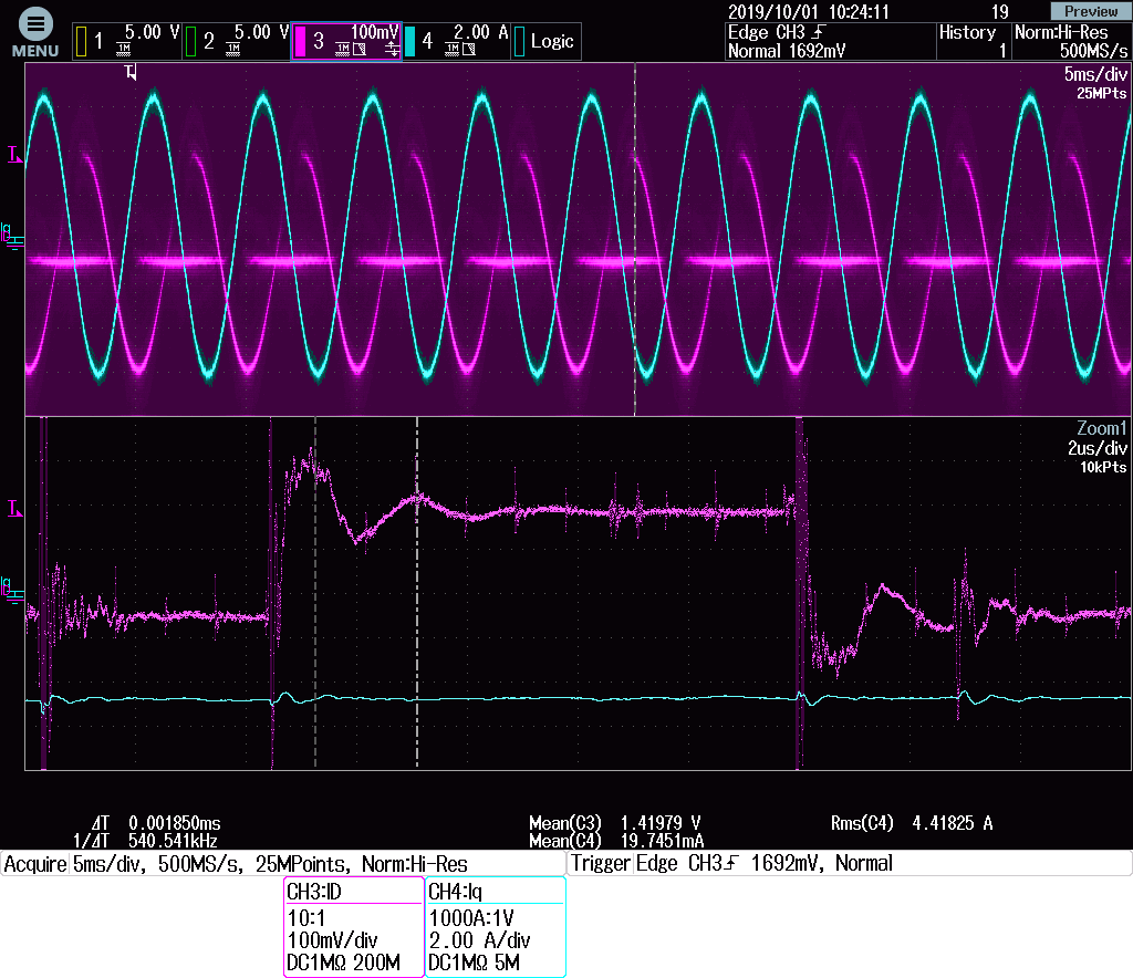
    3. I've connceted 1n dierscly to DRV8323 SOx outputs. It went worse - signal settle with 500Khz ringing. See attachjed picture

  • Mirtcho,

    Thanks for posting on the MD forum!

    Let me ask the team providing your detailed information above and get back to you.

    Regards,

    -Adam

  • Hello Adam,

    Do you have some news.

    In the mean time I've  tryed different approches. Here are my findings.

    1. Use low capaciotance C= 100pF with R=0 or 100Ohm. - Both are running stable.. . The Voltage jump is as expected high. dV=Vin* C_adc/C_external. Vref = 3 worse case dV=3v* 4pf/100pF=0,12V. Settling to 1% takes 300..420ns. - In line with specified. 1200ns @ Gain=40x and step of 0.5V .

    Big voltage jumps and high BW analog input signal reduces ADC performance. 

    Shunt amplifiers dos not have the performance of discrete component - e.g. Op Amps. - settling time takes longer. Delivered output current is limited

    2. Use higher value capacitor and reduce R to the level where amplifier still work stable.  R=470...680Om   C=3,3nF

    Injected AC components is low. This results in better ADC performance on all analog channels

    Handling of high duty cycle becomes problem - Shunt amplifier does not have enough time to settle to low side shunt current.

    Happily this drivers has 3 current measurements. I can use tow of them in case higher duty cycle . E.g. >=95% duty @ 20KHz. The 3-th current I calculate from other two.

    This findings are made via trial and errors. I'm courious to know what is the TI apporoach. Is there any bode plots. available. How can I verify stability  with available DRV8323 datasheet.

    Thanks in advance

    Mirtcho

  • Mirtcho,

    Unfortunately the DRV832x datasheet is limited with respect to the CSA, I agree and apologize.

    We are working on releasing models that would allow this type of situation to be simulated but we do not have those ready yet unfortunately.

    This type of experimentation is common and what we usually suggest as every customer case and board is different.

    Please let us know if we can help more.

    Regards,

    -Adam

  • Hello Adam,

    Thnaks for the feedback.

    I've found an solution for my design using  trial and error approach.

    I've used LtSpice for initial analysis and matching of RC circuit with uController. 

    Later on moved real hardware to tune it against DRV8323 CSA. 

    I have attached the LtSpice circuit. I hope this helps other engineers too.

    Best Regards,

    Mirtcho

    PS; I cannot attach LtSpice schematics. Am I doing something wrong or is just forum limitation

  • Mirtcho,

    You should be able to upload any file, are you getting some error code?

    Regards,

    -Adam

  • Mirtcho,

    Did you get this resolved?

    Regards,

    -Adam

  • Mirtcho,

    I have seen no update on this thread, did your issue get resolved?

    I will mark this thread as closed for now but please post again if you need further assistance.

    Regards,

    -Adam