Other Parts Discussed in Thread: DRV8702-Q1, CSD18540Q5B
Hi,
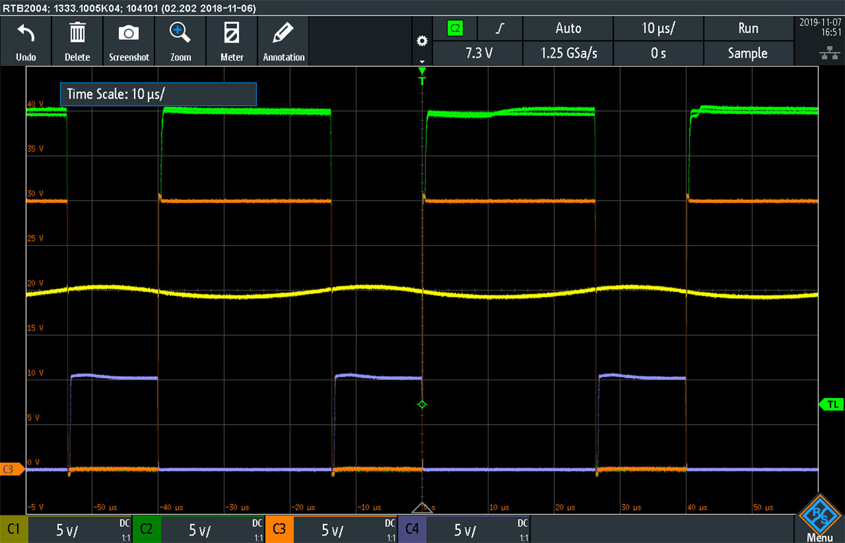
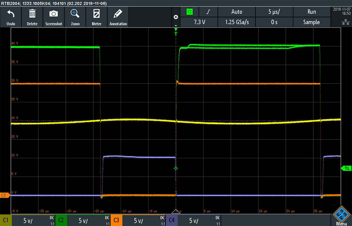
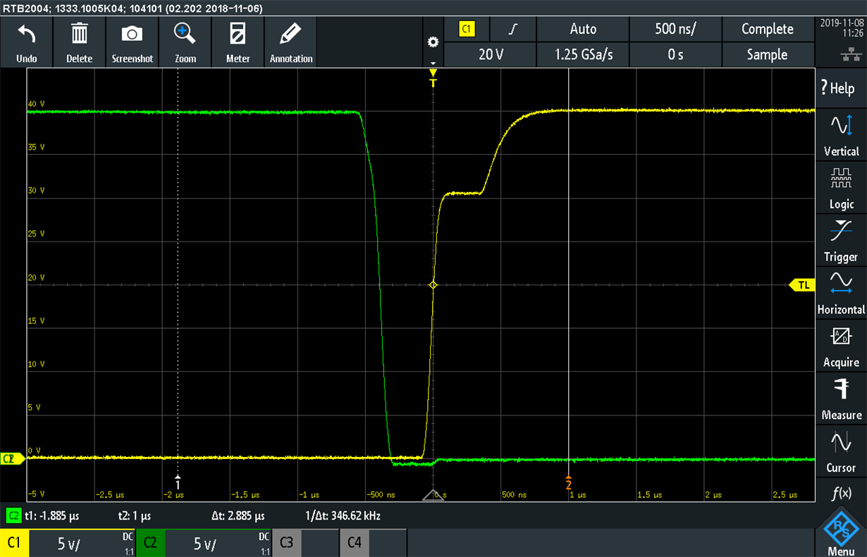
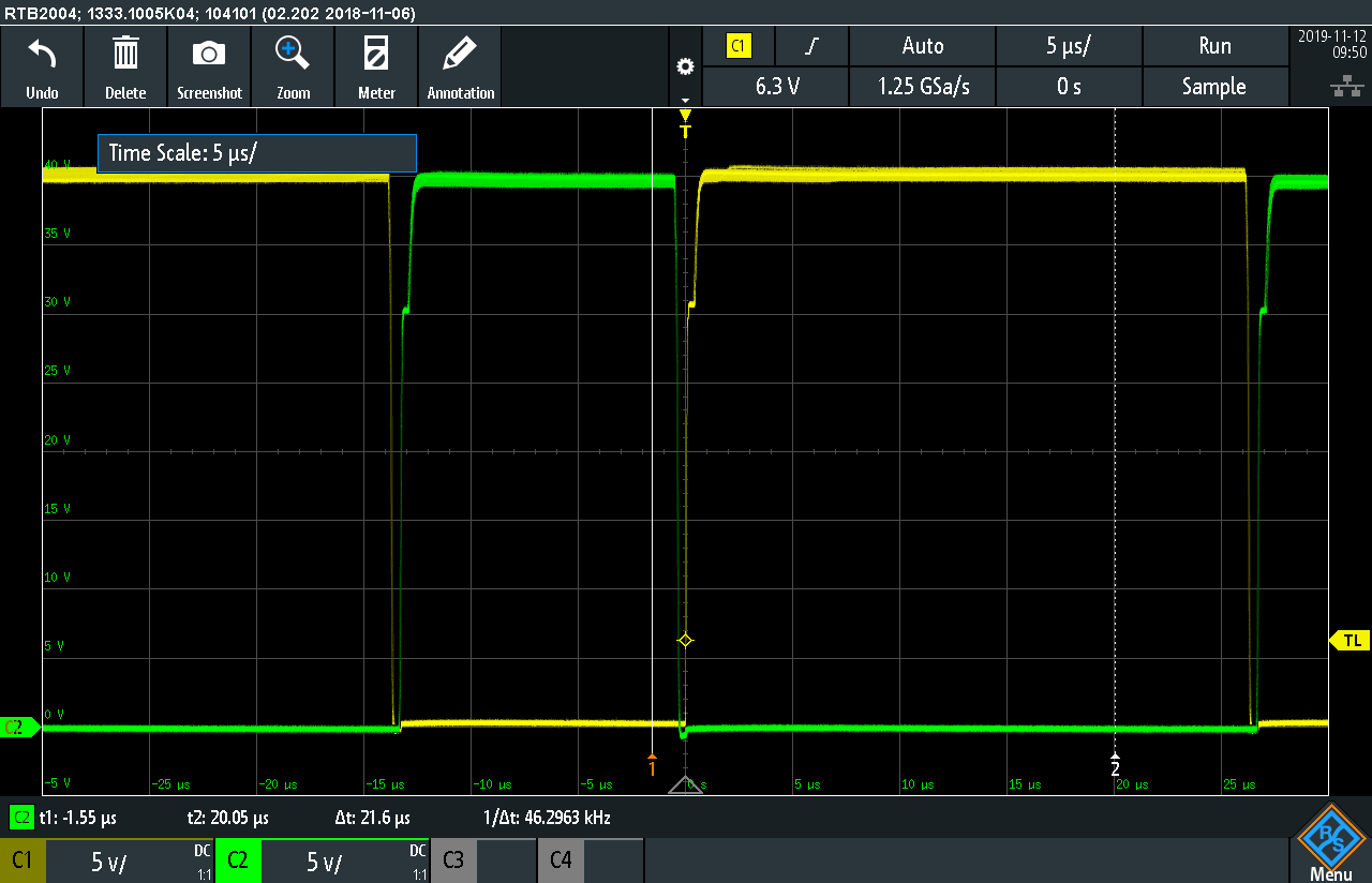
I have a design composed of an Hbridge of CSD18540Q5B, a DRV8702-Q1 and an output filter. The output of the system is supposed to be a sinusoidal voltage from a PWM signal. With no load the system works perfectly, but with a load of let's say 10 ohms, the output voltage drops and the calculated impedance of the amplifier is approx 0.6 Ohm.
Here's a capture of the schematic (half of the bridge)

The inductor used is SRP1770TA-101M, the filter capacitor is PCV1K150MCL1GS and the free wheeling diode is V8PAM10HM3/I.
Can you recognise anything inherently wrong in the design?
Thanks,
Federico