This thread has been locked.

If you have a related question, please click the "Ask a related question" button in the top right corner. The newly created question will be automatically linked to this question.

SM72295: SM72295

Part Number: SM72295

Hello,


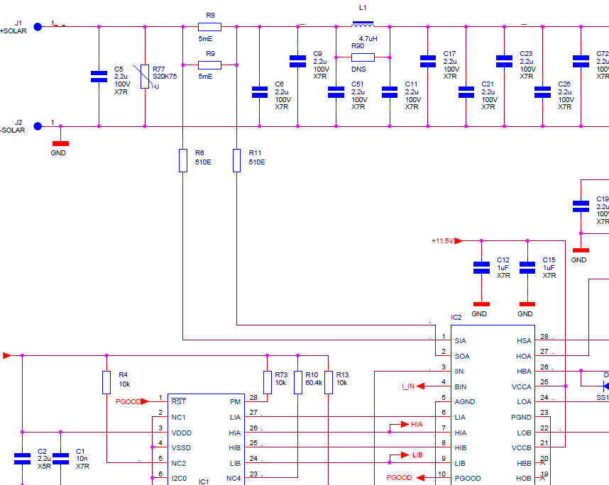
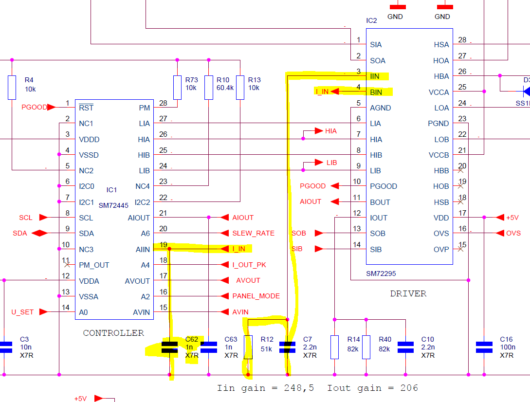
What could be the root cause of a defect input current measurement circuit (SIA~SOA)?

The output of BIN is incorrect. We have drivers with different error behavior: couple of amps error, random output and extreme high output.

The MPP-Tracker does not operate in the MPP of the PV module when the current measurement circuits is defect.

See schematic below, could you provide support.


Best regards,
HOG

  • Hi HOG,

    Welcome to e2e, and thanks for your interest in our products.

    I would suggest checking the following things to debug this issue:

    1. Is the size of your sense resistor appropriate for your current levels? Is it too big or two small? This would cause the op amp to rail out.
    2. Is the signal being fed into SIA and SOA noisy? You might need to add some capacitance to filter the signal if it's extremely noisy. You'll need to look at this differentially.
    3. Is your IIN signal clean? This may require filtering if not.

  • Hi HOG,

    in addition to Don's suggestions add 10nF cap between SIA/SOA similar to page1 of the datasheet diagram.

    The 10nF will help with keeping the voltage between these pins fixed and within spec to achieve an accurate reading.

    You can likewise put a cap on IIN and in parallel with RL to achieve a steady gain.

    Thanks,

  • Hi Jeff and Don, thanks for your reply.

    A cap on Iin and Bin is already there, see schematic below. Is this okay?

    The max specified PV current is 19A, so the shunt value 2.5mE. should be fine.

    Our initial test shows that a 10nF cap between SIA and SOA reduce the noise on the input.

    Do you have experience that the SIA/SOA input without the 10nF can break down overtime?

    Kind regards,

    HOG

    .

  • Hi HOG,

    Sorry for the delay.

    As you found, the 10 nF cap is used to filter noise to make the current measurement more accurate. However, in some applications, you may not need it. In fact, on the EVM, this cap wasn't added: www.ti.com/.../snvu473.pdf

    Make sure your applied voltages are within the Absolute Maximum Ratings for reliability.

    Let us know if you have further questions.
  • Hi HOG,

    Thanks for your reply, sorry for the late reply..
    Can you confirm the voltage on IIN and BIN when not working?
    you said first that BIN was incorrect, during this time is the IIN voltage clean (as Don first asked)?
    does BOUT give you correct results? I see the gain is different, why? (there is R14/R40 in parallel, why?)

    Thanks,
  • Hi HOG,

    how the debug going? were you able to confirm the above?

    Thanks,