This thread has been locked.

If you have a related question, please click the "Ask a related question" button in the top right corner. The newly created question will be automatically linked to this question.

TPS62130: TPS62130: High output at startup.

Part Number: TPS62130

Hello there.

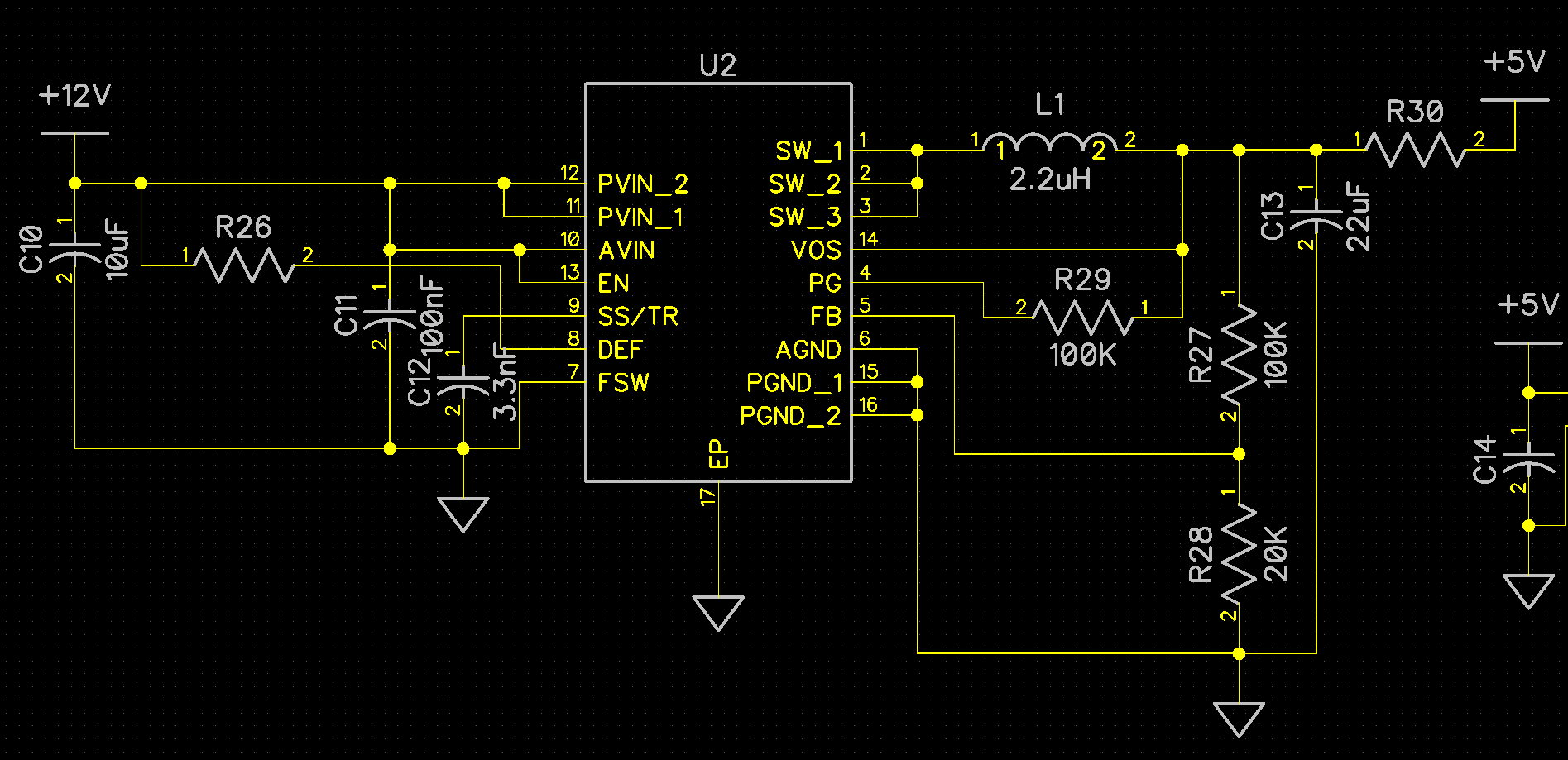
I have designed a board based on the typial schematic and layout recommendations described in the datasheet. I am feeding 12VDC, and generating 5VDC using TPS62130ARGTT. Please note that the enabe pin is shorted to the input supply (as suggested in the datasheet). When I plug in the 12V supply, I receive an output voltage of 9VDC, which linearly diminishes to 5VDC in about 35ms, after which it is stable. The device is working nicely under stability, however the transient behaviour of the device (especially the 9VDC output) is lethal to our system.

It would be really appreciable if someone could suggest any measures to curb this transient behaviour.

  • Abbas,

    Are you hot plugging the 12 V supply?  Can you provide some waveforms of the start up behavior including the SW node voltage?

  • Hello .

    Thank you for responding to my inquiry.

    Yes, we were hot-plugging it. Unfortunately, we can not provide you with the waveforms as shortly after, the output was no longer stable at 5V. It started varying, and stabilized at 7V. After a short while, it stabilized at 9V. And, after another short while, it went straight to 12V (as if in 100% duty cycle mode).

    We had to take up another board, and then we read about the problems several other engineers faced when hot-plugging TPS62130. Now, we are avoiding hot-plugging as much as we can, and it seems to work fine. However, we have noticed a weired behaviour from this switcher. It is rather unstable at no-load. sometimes it works nicely, sometimes it doesn't. We ruined 4 ICs only to understand how it behaves in no-load, but we couldn't. We have been testing it on a moderate (1A) load, and it seems to work fine for a few hours now. However, we still could not develop confidence on this device, whether to use it in our product. I have read posts on your E2E community about this device miserably failing after days/weeks of absolutely fine run.

    I would really appreciate it if you could help me understand the peculiar behaviour of this device under no-load, and why it is "allergic" to hot-plugging.

    Looking forward to hearing back from you soon.

    Warm regards,

    Abbas Mehdi.

  • Hello .

    We are facing serious challenges in stabilizing the output of tis device under light/no-load conditions. The output ramps up to random high voltages, with no certainity. This is causing damage to other devices on that power rail.

    It would be really apprecible if someone could guide us on how to stabilize the output to a fixed voltage with a consistent behaviour at ligjht/no-loads.

    Looking forward to hearing back soon.

    Warm regards,

    Abbas Mehdi.

  • OK!

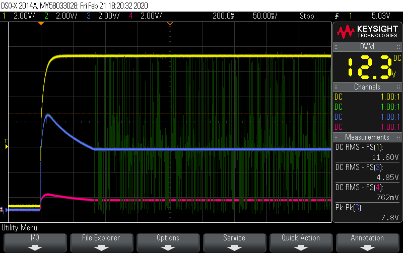
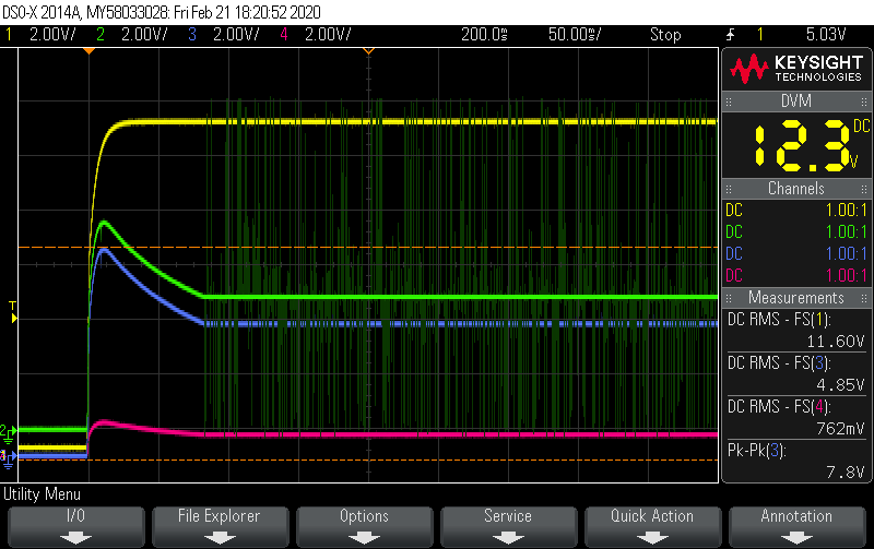
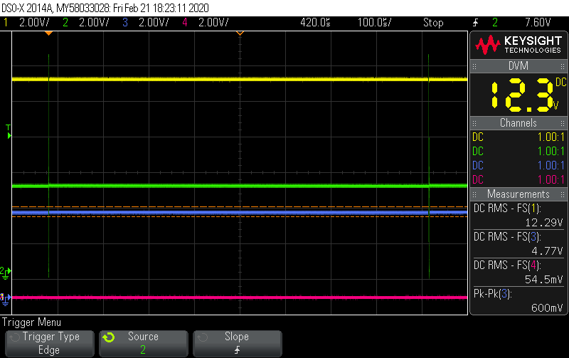
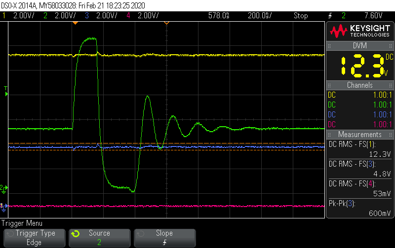
    We are seeing some similar behaviour in another board. Here are the waveforms:

    Channel 1:  Input Voltage , Channel 2: Switching Node, Channel 3: Regulated Output Voltage, Channel 4: Voltage at Feedback pin.

    Channel 1:  Input Voltage , Channel 2: Switching Node (shifted upwards for clarity), Channel 3: Regulated Output Voltage, Channel 4: Voltage at Feedback pin.

    Channel 1:  Input Voltage , Channel 2: Switching Node, Channel 3: Regulated Output Voltage, Channel 4: N/A.

    (Scale zoomed to show time between two swtichings).

    Channel 1:  Input Voltage , Channel 2: Switching Node, Channel 3: Regulated Output Voltage, Channel 4: N/A.

    (Scale zoomed to show the transient response of a single switching).

    The concern is the same; the high outputs being received at power-up (Upto 8V received for a Vout setting of 5V).

    Please note, there is not output load. The device shows this behaviour at no/light loads. At moderate/heavy loading, it works perfectly fine.

    It would be really appreciable if someone could hint on how to limit this power-up shoot?

    Looking forward to hearing back soon.

    Warm regards,

    Abbas Mehdi.

  • Abbas,

    It looks as though something is pulling the output voltage up externally.  Do you have any processors or FPGAs on your board?  It could be pre-bias voltage leaking from another rail.

  • Hello .

    Nope! As I specified in my posts, the problem is faced at no/light-loading.

    We don't have any other device populated on our board, as we need to develop a confidence on the power supply first.

    For load testing, we are connecting external resistive loads to the output of the device (which are not part of the board).

    The regulator is working perfectly fine at moderate/heavy loading.

    Looking forward to hearing back soon.

    Warm regards,

    Abbas Mehdi.

  • Abbas,

    Can I see your schematic?

  • Sure, it's the same as recommended in the datasheet.

    Looking forward to hearing back from you soon.

    Warm regards,

    Abbas.

  • Abbas,

    There is definitely something wrong with you start up behavior.  How any circuits do you have that behave this way?  For 3.3 nF SS capacitor, your output should ramp up to 5 V in approximately 1.65 msec.  During that time, the SW node should start switching immediately with rather low switching frequency.  As the output voltage rises the switching frequency should increase until the end of the soft start time.  Since you do not have any load, the circuit should go into light load operation and only switch occasionally once it reaches regulation.

    In your case, the output and or the SW node is pulled up well above the 5 V regulation point.  Since there is no current in the inductor, both sides will have the same voltage.   It is not possible for me to tell which end is being pulled up, but I suspect it may be leakage from the input side.  With the output voltage very much above the regulation point, the TPS62130A will not switch.  After about 80 msec, the output voltage decays down to 5 V and the device starts switching. You will need to find the source of the initial pull up.  If the boards you are testing have all been hot plugged, it is possible you have damaged the TPS62130A. You may need to repeat this testing with a fresh device.  Let me know if replacing the IC fixes your problem.

  • Thanks for the reply, .

    I don't see the output being pulled to a higher voltage. It is stable at the voltage regulation point. If you are mentioning about the initial (transient) shoot, I suspect it is from the switch closing on power up and not opening back in time to regulate the voltage. By the time it opens back, the output has already shot up.

    I replaced the IC, even populated a fresh board, but the response is the same with no significant differences.

    However, I notices that the settling time (of the initial shoot) is directly related to the soft-start capacitor. removed the 3.3nF cap, and the settling time is reduced from about 90ms to about 30ms. Placed a 220nF cap, and the settling time went up to about 200ms, although the overshoot remains the same.

    Hope you would be able to guide me to how to limit this initial overshoot.

    Looking forward to hearing back from you soon.

    Warm regards,

    Abbas.

  • Hello, .

    I really am grateful to you for your willingness to help me resolve my problem.

    I found the cause of that power-up shoot, and it seems like you were partly correct in guessing that something is pulling the output rail.

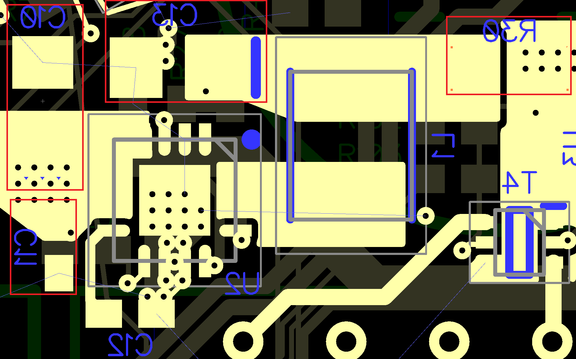
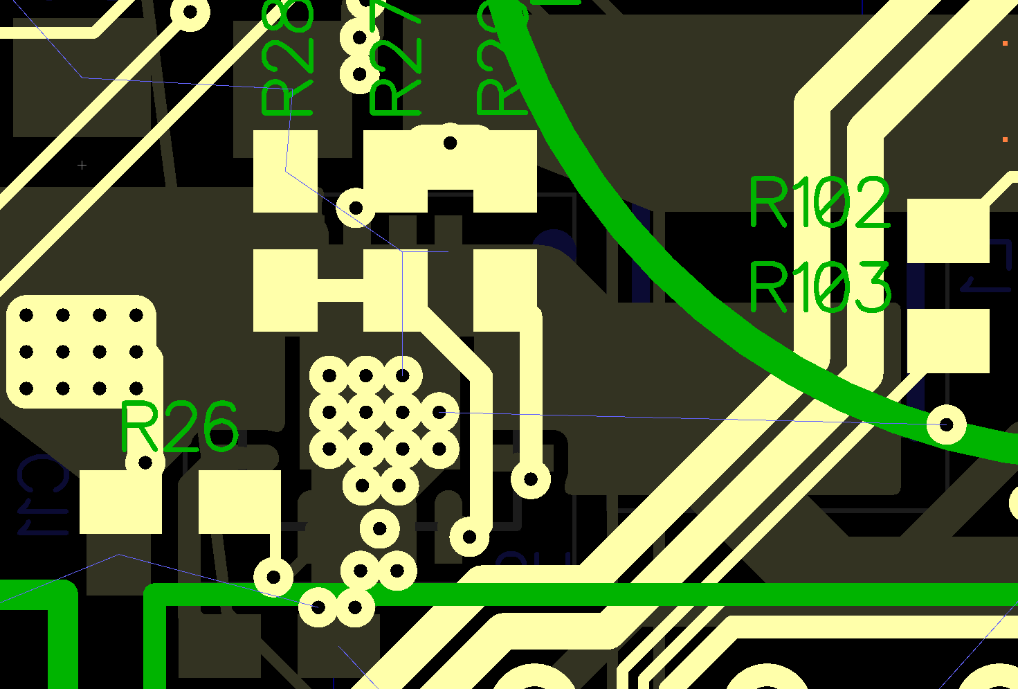
    In our board, a thick track of the input rail (12V) runs quite a distance in parallel (physically) to the copper pour connected to the output rail (5V). We couldn't suspect this in our wildest dreams, but when measured, there seems a stray capacitance of 2uF to have been developed between the input and output rails. This capacitive coupling is what is causing the power-up shoot. The device is perfectly fine, and the culprit seems to be this bad layout.

    Thank you once again for your time.

    Warm regards,

    Abbas Mehdi.