This thread has been locked.

If you have a related question, please click the "Ask a related question" button in the top right corner. The newly created question will be automatically linked to this question.

Crashing on BQ24075 Vout depsite stable voltage on Vin

Other Parts Discussed in Thread: BQ24075

Hi Everyone,


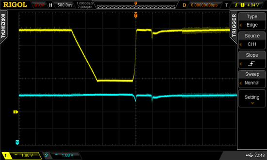
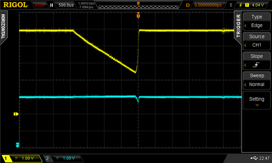
I'm using the BQ24075 to charge at battery from a USB input while running my application. I'm finding however the output supply of the BQ24075 (which is connected to two regulators providing 3.3V and 5V respectively) is crashing approximately every 600ms, this crash lasts for around 2ms in duration. The voltage appears to crash from around 4.9V to approximately 2V at the output (pins 10,11) - shown in Yellow on the plots below. Note, in this testing/configuration I have disconnected the battery, it is not present or connected to the system.


I find that I'm getting two crashes that consistently occur, one after the other. This is shown in the following oscilloscope plots. These two pulses each occur 1200ms apart and are offset from one another by 600ms.


From my testing I would conclude the following:

  1. Both plots are essentially showing the same issue. The duration of the crash is the same, as well as the voltages (approximately).
  2. In the first part of the crash, the plots are showing the constant current (linear) discharge from the input capacitors at the regulators. I.e. the regulators are attempting to draw X mA of current to provide either 3.3V or 5V respectively at a given load.
  3. The input on pin 13, is practically stable, it varies a little between 4.9 and 5.1V, nothing that wouldn't be expected though. There is a small drop of voltage on the input line following what I assume to be Q1 (inside BQ24075) switching back on at the end of the crash, causing a small inrush of current from input pin 13.
  4. The reason for the two different waveforms, is that my system is attempting to start up in the first scope capture. Since the current draw is higher during start up, we see a steeper drop in the input capacitors at the regulators who are drawing more current to meet the system startup load. The result of this is my micro-controller rebooting approximately every second as once the voltage at pins 10,11 drops below a threshold voltage, the 3.3V regulator cuts out.

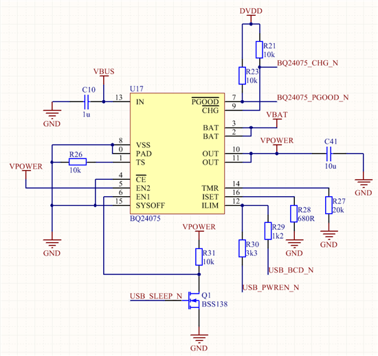
Here is diagram of my application:

VBUS - 5V input from USB
VPOWER - output voltage from BQ24075, connected to regulator inputs via 34.7uF of capacitance (parallel combination of 10uF at BQ24075, 10uF at 3.3V regulator, 14.7uF at 5V regulator)
VBAT - connected to the battery (no battery present / disconnected, note: 4.2MOhm path to ground exists via a fuel gauge)
DVDD - 3.3V supply from regulator, used to power the micro-controller and pull up the CHG_N and PGOOD_N signals.

USB_BCD_N - (Not Battery charger detected) - currently tied to ground to eliminate this variable (confirmed stable at zero volts)
USB_PWREN_N - (Power enable) - currently set to high impedance to eliminate this variable
USB_SLEEP_N - Currently set to drive one to eliminate this variable (confirmed stable at 3.3V, above Vds of the inverting MOSFET).

This combination gives EN1 = 0, EN2 = 1; input current controlled by ILIM.

With USB_BCD_N = 0, and USB_PWREN_N = Z, resistance at ILIM should be 1k2, allowing for approximately 1.42A of current to be drawn from IN at pin 13.

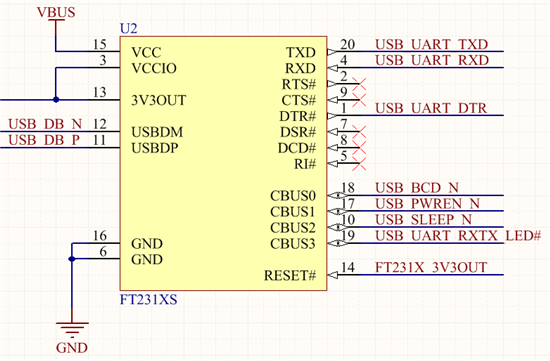
As a minor side note, the USB_*_N signals are connected up to a FT231X UART USB bridge with battery charging detection. To simplify testing and analysis, I have temporarily programmed the CBUS pins to either drive 1, drive 0 or be tri-stated as per the notes above. Both scope captures above were taken in this configuation to eliminate any issues coming from the FT231XS.


Well, that is about as much as I can think of for the moment, I hope I have provided enough information about my application to help you understand the presented issue. However if you need more information, please respond and I'll gladly post up other scope captures of different signals or parts of my circuit.


All the best,

  • Can you confirm the SYS load current by taking a scope plot of the current and powering the system directly from a power a supply (i.e. bypass the bq24075)?

    Is the IC running in supplement mode because the SYS load is higher than ILIM allows and therefore connecting SYS to BAT?

  • Hi Jeff,

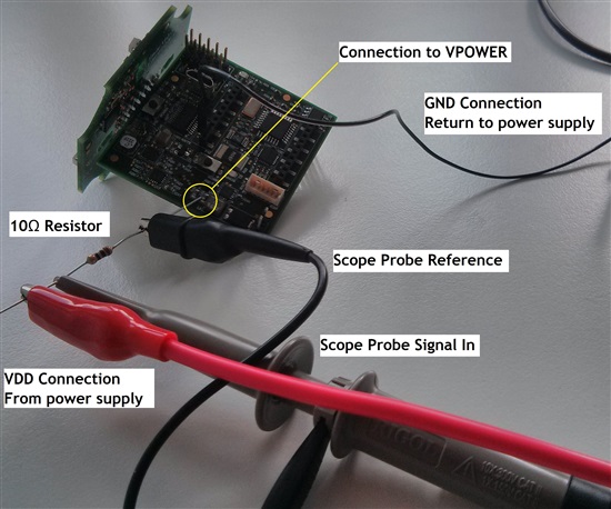
    Here is a plot of the SYS current. I have used a laboratory DC power supply to provide 4.9V up to a maximum of 500mA. In series with the DC power supply is a 10 Ohm resistor (couldn't find any 1 Ohm resistors around). I measure the voltage drop across this resistor with my probe. Note, BQ24075 is still in the circuit, although there is no voltage on the input power pin. here is a photo of the setup:

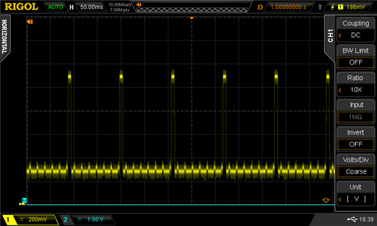
    And here is the resulting plot of the voltage across the resistor:

    So, if I have the numbers right, we have an average current draw of around 30mA, with a pulse draw of 110mA lasting around 10ms approximately every 110ms. The signal is a bit noisy, although I think this is reasonable considering the thermal noise from the resistor and the fact that we are feeding switching regulators with this input voltage.

    Anyway this seems to be well within the allowable current that I configured for ILIM,

    Here are my calculations, the relevant case for the current configuration of the FT231XS (with respect to the override at the CBUS pins) is case 3:

    K_ILIM (0.2A - 0.5A) {1330, 1525, 1720}
    K_ILIM (0.5A - 1.5A) {1500, 1610, 1720}
     
    Case 1: BCD_N : Not-asserted, PWREN_N : Not-asserted
    80mA (SDP - Not Enumerated)
    ILIM = High Z, no charging
     
    Case 2: BCD_N : Not-asserted, PWREN_N : Asserted
    480mA (SDP - Enumerated)
    K_ILIM = 1500
    ILIM = 480
    R_LIM_SDP = K_LIM / I_LIM = 3.125kOhms => 3.3kOhms
    (ILIM = 455mA)
     
    Case 3:  BCD_N : Asserted, PWREN_N : Not-asserted
    1480mA (DCP)
    K_ILIM = 1700
    ILIM = 1480
    R_LIM_SDP = K_LIM / I_LIM = 1.148kOhms => 1.2kOhms
    (ILIM = 1.42A)

    Thanks for reply Jeff, I hope this helps!


    Cheers,

  • Some more oscilloscope traces for the fun of it.

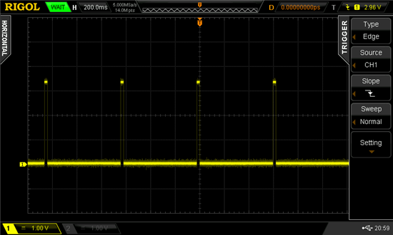
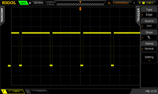
    I have found that the PGOOD_N and CHG_N indicator pins are also pulsing to what should be invalid levels at 600ms intervals. Both PGOOD_N and CHG_N are pulled up to DVDD (3.3V) with a 10k resistor. They are then attached to the inputs of microcontroller (port direction, pull up configuration etc has been verified) for monitoring the BQ24075.

    The plot above shows PGOOD_N, which should always be low, as the USB is plugged in during this capture and the USB power is stable.

    This next plot shows CHG_N, should always be high, as there is no battery attached to the system.

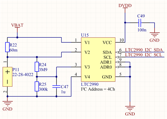
    These plots now make me curious whether the BQ24075 is getting confused by the presence of my battery gauge circuit which is as shown below:

    V1,V2 (differential) measures the discharge, charging current and V3,V4 (differential) measures the battery voltage (scaled down to +/-0.3V to comply with the differential mode rating)


    Cheers,

  • Just a follow up post, after several days of testing I was able to conclude that it was indeed my battery current and voltage measurement circuitry that was responsible for the glitches. Either connecting the battery to the circuit as well as removing R24 and short circuiting R22 caused the glitch to disappear.

    I don't have time to look into this any deeper, but I can only assume the control loop that detects the presence of a battery and initiates the charging circuitry was getting confused by the passive network formed by R22, R24, R25 and C47.