This thread has been locked.

If you have a related question, please click the "Ask a related question" button in the top right corner. The newly created question will be automatically linked to this question.

BQ25713: Advice on 4S4P Battery to charge

Part Number: BQ25713
Other Parts Discussed in Thread: BQ24610, CSD17551Q3A, CSD17578Q3A

Hello,

I was wondering if the battery charge would be capable of charging an Ansmann 4S4P battery, The amount of cell the battery pack has is 16 Cells

Nominal Voltage of 14.8V and a nominal capacity of 13800mAh

I understand it mentions from 1-4S and 1-6S but would you think the BQ25713 and the BQ24610 would be capable of charging this battery packs safely? Also, is it possible to restrict the charging rate to 4A? 

I hope to hear from you soon!

Best regards

Mo

  • Hi Mo,

    The bq25713 and the bq24610 are both capable of charging your battery. We only count the number of series cells, so a 4s4p battery is 4 cells, not 16. The number of series cells determines the battery voltage, while the number of parallel cells determines the battery capacity. Therefore, the number of series cells is what matters because that determines which chargers are suitable for a given battery, while the number of parallel cells just changes the charging time.

    The bq24610 is standalone, so you can use a resistor divider to control the voltage on the ISET1 pin, which sets the fast charge current (please see Section 9.3.2 in the datasheet for more details).
    The bq25713 is host-controlled, so you can use I2C to write to the ChargeCurrent Register and set it between 64 mA and 8.128 A (please see Section 9.6.3 in the datasheet for more details).
    In either case, you can certainly restrict the charging rate to 4 A.

    Best Regards,
    Angelo Zhang
    Applications Engineer | Battery Charging Products

  • Mo,

    Both BQ25713 and the BQ24610 can support 4S4P battery with tight charge current regulation control. At 4A with 10mohm current sense resistor, the BQ24610 charge current regulation tolerance is +/-3%; BQ25713 is -3% to 2%.
  • Ah that is brilliant thank you for you advise. I do have one more question, if I restrict the charging current to 4A can I run the system load at the same time?

    My system load is approximately 4.2A

    Best regards

    Mo

  • Hi Mo,

    Can you tell us the current and voltage ratings for your adapter?

    The bq24610 and the bq25713 both have Iindpm and power path. What this means is that if your system and battery are drawing more current than your adapter can provide, then the charger will prioritize the system and reduce the charging current for the battery. For example, if your adapter can only provide 6 A, your battery charge current is set to 4 A, and your system draws 4.2 A, then the charge current will drop so that the charger can provide the 4.2 A needed by your system to operate.

    Therefore, the short answer is yes because both of these chargers will prioritize the system over the battery, but you should also pay attention to your adapter's specs.

    Best Regards,

    Angelo Zhang

    Applications Engineer | Battery Charging Products

  • Hello Angelo,

    You are correct on saying 6A, our power supply will be providing only up to 6A at 24V. Which is good as this is what I wanted to expect, and thank you for confirming.

    I did notice something else which maybe an issue, BQ25713 page 73 mentions about the Power MOSFETs Selection, I was using the standard reference components from the eval board (www.ti.com/.../BQ25713EVM-017) the MOSFETs are of 30V but it is said to be recomemnded 19V to 20V can you confirm that the MOSFETs on the Eval board ok to use as the BQ25713 datasheet says otherwise (page 73).
    Also, CSD17551Q3A MOSFET is not recommended for new designs can you confirm that CSD17578Q3A would be the best alternative?

    Also, I wanted to just notify you about Page 71 of the BQ25713 datasheet some of the resistor and capcitors don't have any values and some resistors are explained as "kW" which i believe it to be a typo.

    I hope to hear from you.

    Best regards

    Mo
  • Hi Mo,

    Regarding power MOSFET selection, the datasheet says that for applications with 19-20 V input, it's preferred to use MOSFETs with 30 V or higher voltage ratings. It doesn't mean that you have to use MOSFETs with specifically 19-20 V voltage ratings. Just wanted to clear that up since it seems like there might have been a misunderstanding there.

    Yes, the CSD17578Q3A would be a good choice. Its voltage and current ratings are sufficient for your application.

    Regarding the missing and incorrect values on page 71, thanks for bringing that to our attention! In general, the application diagram in datasheets is a simplified schematic. We recommend looking at the schematic in the User Guide (Figure 7 on page 15) for more details.

    Best Regards,
    Angelo Zhang
    Applications Engineer | Battery Charging Products
  • Hello Angelo,

    I see I understand the the rating but would you still recommend 30V MOSFETs for 24V input or would I go higher, if so what would be recommeded or should look out for specification wise?

    Best regards

    Mohammed Al-Amin
  • Hi Mo,

    The CSD17578Q3A is still recommended.

    The CSD17551Q3A was chosen in the EVM schematic because it can support a max drain-to-source voltage of 30 V, a max gate-to-source voltage of +/- 20 V, and a max drain current of 12 A at Ta = 25 °C. This is sufficient because the bq25713's max input voltage is 24 V, the gate drive voltages for the power MOSFETs are 6 V, and the max charge current is 8.128 A.

    The CSD17578Q3A has similar specs, but it can support a max drain current of 14 A at Ta = 25 °C, so it will certainly work in your application. Another benefit is that it has the same functionality and pinout, so it's easy to substitute into the EVM schematic.

    If you prefer, you could also look into 40 V MOSFETs, but those are considered mid-voltage instead of low-voltage, and they're often designed to support drain currents of 100 A or more, which is overkill for your application.

    Best Regards,
    Angelo Zhang
    Applications Engineer | Battery Charging Products
  • Hello,

    Thank you Angelo, I will stick the recommended, I wanted to know the reason why so I can justify making changes.

    I will comment back on here if I come to any issues with the schematic design and thank you again for all the help.

    Best regards

    Mo

  • Hello,

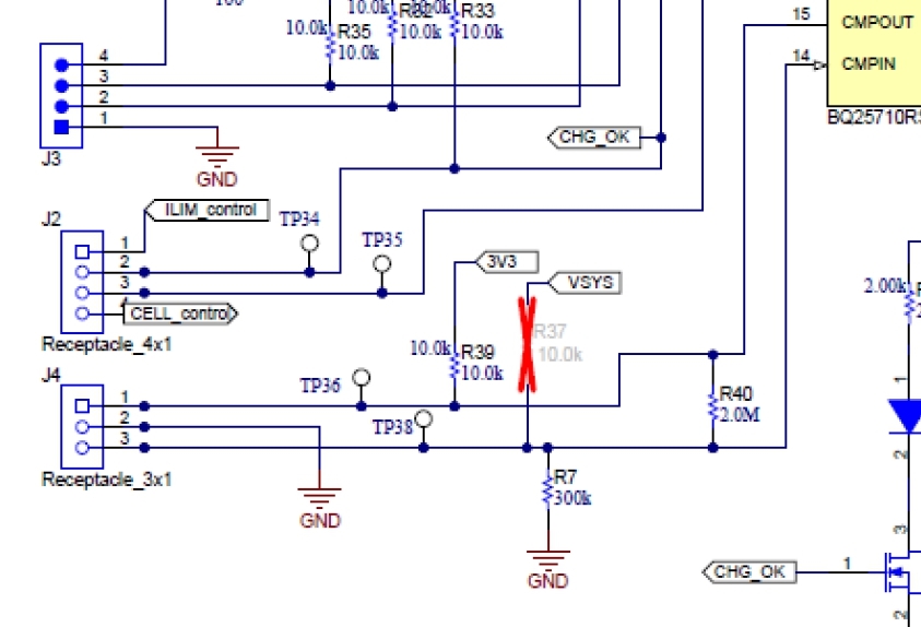
    I was going through each part from the BQ2571x Evaluation Module component parts.

    From the Bill of materials so far R7, C50, C51, C52, C53, C54 and C55 are not identified for consistancy in the Bill of materials.

    Thank you.

    Mo
  • Hi Mo,

    Thanks for bringing that to our attention!

    You're correct; R7 is given as 300 kΩ in the schematic, but it isn't listed in the BOM. R7 = 300 kΩ is the correct value.


    C53 is even more unusual. It's given as 33 µF with a 35 V rating in the schematic, but the BOM says it's 47 µF with a 20 V rating. I've just checked up on that issue, and the schematic is correct. C53 = 33 µF with a 35 V rating.

    C50, C51, C52, C54, and C55 are crossed out in the schematic, and they are not needed in your circuit.

    Best Regards,

    Angelo Zhang

    Applications Engineer | Battery Charging Products

  • Also to add to this I have noticed that The polarised caps named C2, C48, C49,C53, C54 are named on the circuit at 33uF 35V, but on the BOM it listed at 47uF 20V.

    Please, can you confirm which would be correct, also C2 is not listed on the BOM.

    Thank you 

    Mo

  • Hi Mo,

    I've just checked up on those component values.

    C2 is listed as 47 uF in both the schematic and the BOM, but it's crossed out anyway, so you don't need to include it in your circuit.

    C48, C49, and C53 should all be 33 uF with a 35 V rating. The values in the schematic are correct, but the BOM is wrong.

    C54 isn't listed in the BOM, but it's also crossed out, so you don't need it in your circuit.

    To summarize, C2 and C54 are not needed, and the correct values for C48, C49, and C53 are shown below.

    Sorry you've encountered all these discrepancies! We'll be updating the EVM user guide to fix these issues in the next month or so.

    Best Regards,

    Angelo Zhang

    Applications Engineer | Battery Charging Products

  • Thank you Angelo,

    Would I have to consider putting in the footprints of the unused components for the future or is this unnecessary extra work?

    Best regards

    mo

  • Hi Mo,

    The unused components are unnecessary. You can safely leave them out of your design.

    Best Regards,
    Angelo Zhang
    Applications Engineer | Battery Charging Products
  • Hello Angelo,

    Thank you for letting me know for R37 as it is not needed would I disconnect VSYS from CMPIN altogether?

    Best regard

    Mo

  • Hi Mo,

    Yes, that is correct. VSYS would be disconnected.

    Best Regards,
    Angelo Zhang
    Applications Engineer | Battery Charging Products