This thread has been locked.

If you have a related question, please click the "Ask a related question" button in the top right corner. The newly created question will be automatically linked to this question.

BQ40Z60 - Battery Pack Charging Current too HIGH

Other Parts Discussed in Thread: BQ40Z60

Hi,

I made my own BQ40Z60 PCB based on original TI's EVM. Everything works great except charging current control. It looks there is no control.

I'm using  4-cells of US18650V3 in 4S configuration. Device connected to VSYS generates about 2000mA constant load. I changed "Rec Temp Charging" current values to 2800mA.

Everything works great when battery pack is fully charged. After start using battery pack energy, when discharge current exceeds 2800mA (+/-30% state of charge) plugging back adapter only reduces current from pack but BQ40Z60 doesn't want to start charging it. If I increase "Rec Temp Charging" current values i.e. to 4000mA charger works good up to the moment when system load reaches  i.e. 0mA (no load), then batt. pack charging current exceeds max continous charging current (from cell's datasheet = 2150mA).

Is it possible to set Charging Current on enough high level i.e. 4000mA, and separatelly max charging current for batt. pack, i.e. 2150mA or lower?? How to resolve this problem?

  • You should set the charging current parameters to the limits that you want to charge the cells without a load on VSYS. The charger should allow the current to reach this level and you will see it reduce as the current tapers near the end of charge. If a load is applied to VSYS while charging is in process, then the current will go to the load first and then excess current will go to the cells. Only the current to the cells will be reported in the Current parameter. Current to the load, from the charger, will not go through the coulomb count sense resistor and does not get reported.
  • OK, but my load applied to VSYS needs higher current limit than limit for charging my cells, in this case BQ40Z60 will let to discharge battery pack to meet the demand for energy - how to prevent this situation? What to do now?

  • ThomasCosby said:
    Only the current to the cells will be reported in the Current parameter. Current to the load, from the charger, will not go through the coulomb count sense resistor and does not get reported.

    In other words the current to the cells is only reported (coulomb count), but not used in control loop (also shown in Fig. 6 of SLUSAW3C)?

  • Yes, that is correct. the charger sense resistor controls the current in the charger.
  • However that doesn't answer the OP question. 

    What do we do if we want to extract more power from the PSU?
    Say the PSU supplies 5A, battery is set to charge at 2A, and load current is 4A. I would want to have 4A from PSU to load, and 1A to battery (charging). Instead we get 2A from PSU, and 2A discharge from battery pack. 

    Is there something I'm missing here?

    The current sense resistor is connected between PSU and load + battery here, according to Power Path Overview on the datasheet. In this case the current sense resistor tells the BQ40Z60 the current being drawn from the PSU, and not really what is going into or coming from the battery. 
    What my application requires is that the power be monitored to the battery, and all the excess be available to the load, with the battery supplying power only when PSU falls short. 

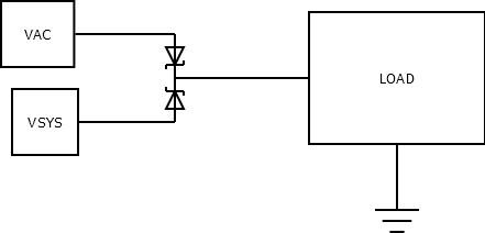
  • Maybe, you have to do something like this:

    So, when there is the adapter voltage, the load is powered through the adapter. When the adapter voltage goes down VSTS, load is powered through batteries.

  • You should be able to power the load and charge the cells at the same time. Current will go to the load first and then excess current will charge the cells. Please provide an srec file and I will try your parameter setup.