This thread has been locked.

If you have a related question, please click the "Ask a related question" button in the top right corner. The newly created question will be automatically linked to this question.

BQ78350-R1: With a micro-controller connected via SMBUS, what initialization/configuration is required to interface with the said Battery Management System(BMS)?

Part Number: BQ78350-R1
Other Parts Discussed in Thread: BQ78350, BQ76940, MSP430G2553, BQ76940EVM, MSP430FR5994, MSP430WARE, MSP-EXP430FR5994, MSP430F5338, BQSTUDIO

TRM goes over various aspects of Battery management, including configuring/programming the registers to enable/disable certain features. However, since I only need to interface with the BMS from the micro-controller in order to get/query data from the configured values from the BQ78350-R1, is there a list of initializations or configurations to be made in order to read the required values?

  • Hi,
    you need to establish the smbus communication first according to the smbus protocal in the datasheet and TRM,
    then send a read command to the register that you want to read
  • Would you mind pointing me to the section that does just that? Thanks!

    Also if there is already an example of doing such a thing, that would be very beneficial!

  • Hi Jan,

    There is no specific configuration that you need to do with the BQ78350.

    Usually, you configure the BQ78350 with BQ Studio (you need an EV2300 or EV23400 for that), and then all the settings are stored in the BQ's flash.

    The interface with a microcontroller is then used to monitor the battery rather than control it (you can still chnage the settings with your microcontroller if you wanted). But no specific configuration is required at startup.

    I just posted some code for the SMBus for an MSP430 microcontroller in this other thread which you can use:

    Regards,

    Michel

  • Thanks, Michel! Was wondering if you know where I could find the c# equivalent of those files, otherwise I'll need to convert your C code.

  • Those are my own sources that I used with an MSP430 microcontroller. I don't have a C# equivalent.

    Actually, I have never used a microcontroller that used C# for its source.

    Regards,

    Michel

  • Thanks, Michel for sharing code. I think it might be useful to see where and how you call those functions defined in the .c file. Would you mind sharing that?

  • Hi Jan,

    Unfortunately, I can't reveal the whole code.

    In short, we have a state machine that periodically reads the status of the battery through SMBus and then acts upon those readings.

    I can share bits and pieces:

    For example to read battery voltage, you would do this:

    // 0x09 corresponds to the register address of the battery voltage
    // The 2nd parameter (0) corresponds to the index of the command that we sent (used in the callback)
    // batt_data_buffer is the buffer where to store the data
    // battery_rx_done is a callback function called by the SMBus interface to indicate that the data was read
    smbus_requestWord(0x09, 0, batt_data_buffer, battery_rx_done);

    And to read the Operation status (done through manufacturer access command):

    // The 0x0054 parameter corresponds to the command ID in the Manufacturer access
    // The 2nd parameter (1) corresponds to the index of the command that we sent (used in the callback)
    // batt_data_buffer is the buffer where to store the data
    // battery_rx_done is a callback function called by the SMBus interface to indicate that the data was read
    smbus_requestMfrAccessReg(0x0054, 1, batt_data_buffer, battery_rx_done);

    The battery_rx_done callback function is used by the SMBus to indicate that data was received. It contains a switch case, which then copies data to the appropriate location

    void battery_rx_done(unsigned char id) {
      switch (id) {
      case 0: //voltage
        voltage = batt_data_buffer[0] | (batt_data_buffer[1] << 8);
        break;
      case 1: // operation status
        operation_status[0] = batt_data_buffer[6];
        operation_status[1] = batt_data_buffer[5];
        operation_status[2] = batt_data_buffer[4];
        operation_status[3] = batt_data_buffer[3];
    
        // check if we have a permanent failure
        if (operation_status[2] & 0x10) {
          // Permanent failure detected
          failure_detected = 1;
        }
        break;
        ....
        ....
      }
    }

    It will be up to you to figure out what you will need, where and how you will use the data that you read.

    Regards,

    Michel

  • Hello, Terry.

    Does TI have any sample code or guide to establish this communication (bq783650<->MCU via SMBUS)?
    It would be really good if you have or could develop something like the I2C Communication Sample Code for the bq76940 with a CRC Option Based on the MSP430G2553 (www.ti.com/.../slva626b.pdf).

    Regards,
  • Hi,
    I haven't got some code on my hand. It is probably need to edit the codes by users.
  • Hello, Terry and Michel.

    I'm trying to implement a pretty simple code with MSP430FR5994 (Launch Pad) to read the battery voltage of bq76940EVM via SMBUS.

    I'm basing on the SLAA476A example for battery chargers and on the code provided by Michel.

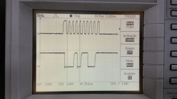
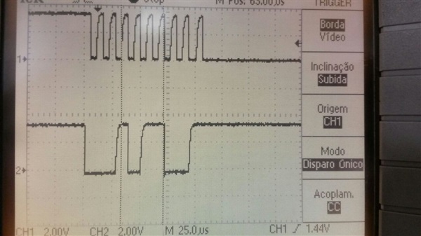
    Unfortunately, I'm not getting any success. When I run the code, the only frame that is sent is the one shown below.


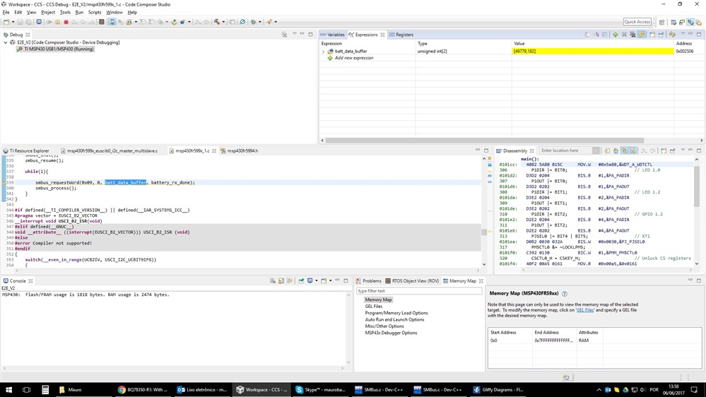
    When I put some breakpoints in the code, it  always stuck in SMBus_NotReady() or in case 4 of interruption, when I comment it.

    What am I doing wrong? Do you have any tips? Where should I look at?

    Code:

    smbus.h

    #ifndef SMBUS_H_
    #define SMBUS_H_
    
    // Generic Definitions
    #define SMBUS_MASTER_MODE_WRITE 0x00
    #define SMBUS_MASTER_MODE_READ 0x01
    #define SMBUS_SLAVE_MODE_WRITE 0x02
    #define SMBUS_SLAVE_MODE_READ 0x03
    #define SMBUS_MSP430_ADDRESS 0x09
    #define SMBUS_SLAVE_ADDRESS 0x16
    #define BQ78350_ADDR 0x16
    #define DESIGN_VOLTAGE_VALUE 48000 // Units (mV)
    
    #define FLAG_SUCCESS 0
    #define FLAG_FAIL 1
    #define FLAG_NACK 2
    
    #define SMBUS_PEC_PASS 0
    #define SMBUS_PEC_FAIL 1
    #define CRC8_POLY 0x07
    #define CRC8_INIT_REM 0x0
    
    // SMBus Data Declarations
    #define SMBUS_DATA_TO_SLAVE 32 // Transmit Table Length
    #define SMBUS_DATA_FROM_SLAVE 32 // Receive Table Length
    
    // SMBus Command Definitions
    #define SBS_CMD_TEMPERATURE 0x08
    #define SBS_CMD_VOLTAGE 0x09
    #define SBS_CMD_CURRENT 0x0A
    #define SBS_CMD_AVERAGE_CURRENT 0x0B
    #define SBS_CMD_RELATIVE_STATE_OF_CHARGE 0x0D
    #define SBS_CMD_CHARGING_CURRENT 0x14
    #define SBS_CMD_CHARGING_VOLTAGE 0x15
    #define SBS_CMD_BATTERY_STATUS 0x16
    #define SBS_CMD_DESIGN_VOLTAGE 0x19
    #define SBS_CMD_MANUFACTURER_NAME 0x20
    #define SBS_CMD_DEVICE_NAME 0x21
    #define SBS_CMD_CELL_VOLTAGE_4 0x3C
    #define SBS_CMD_CELL_VOLTAGE_3 0x3D
    #define SBS_CMD_CELL_VOLTAGE_2 0x3E
    #define SBS_CMD_CELL_VOLTAGE_1 0x3F
    
    // SBS Battery Status Register Bits
    #define SBS_REG_BATTERYSTATUS_OCA BITF // Over Charged Alarm
    #define SBS_REG_BATTERYSTATUS_TCA BITE // Terminate Charge Alarm
    #define SBS_REG_BATTERYSTATUS_OTA BITC // Over Temperature Alarm
    #define SBS_REG_BATTERYSTATUS_FC BIT5 // Fully Charged
    
    #define BUS_1 1
    #define BUS_2 2
    
    #define SMBUS_MASTER_MODE 0
    #define SMBUS_SLAVE_MODE 1
    
    #define SMBUS_START_FLAG_SET 1
    #define SMBUS_START_FLAG_RESET 0
    
    // External Global Variable Declarations
    extern unsigned char SMBus_Data_To_Slave[SMBUS_DATA_TO_SLAVE];
    extern unsigned char SMBus_Data_From_Slave[SMBUS_DATA_FROM_SLAVE];
    extern unsigned char *pTXData; // Pointer to TX data
    extern unsigned char TXByteCounter;
    extern unsigned char *pRXData; // Pointer to RX data
    extern unsigned char RXByteCounter;
    extern unsigned char RXFlag; // Data Received Flag
    extern unsigned char TXFlag; // Data Transmitted Flag
    extern unsigned char RWFlag; // Read/Write Flag
    extern unsigned char SMBus_Start_Flag;
    
    extern unsigned char size_in_bytes;
    extern unsigned char smbus_command;
    
    // Function Prototypes
    unsigned char SMBus_NotReady();
    static unsigned short crc8MakeBitwise(unsigned char CRC, unsigned char Poly, unsigned char *Pmsg, unsigned int Msg_Size);
    
    #endif /*SMBUS_H_*/

    main.c

    #include <msp430.h>
    #include <SMBus.h>
    
    // Global Variables
    unsigned char SMBus_Data_To_Slave[SMBUS_DATA_TO_SLAVE];
    unsigned char SMBus_Data_From_Slave[SMBUS_DATA_FROM_SLAVE];
    unsigned char *pTXData = 0x0;                       // Pointer to TX data
    unsigned char TXByteCounter = 0;
    unsigned char *pRXData = 0x0;                       // Pointer to RX data
    unsigned char RXByteCounter = 0;
    unsigned char RXFlag = FLAG_FAIL;                   // Data Received Flag
    unsigned char TXFlag = FLAG_FAIL;                   // Data Transmitted Flag
    unsigned char RWFlag = SMBUS_MASTER_MODE_READ;      // Read/Write Flag
    unsigned char SMBus_Start_Flag = SMBUS_START_FLAG_RESET;    // Has a transaction been started?
    
    unsigned char smbus_access_status = 0x0;
    unsigned char crc_msg_size = 0;
    unsigned char crc_msg[5];
    unsigned char crc_master_generated = 0;
    unsigned char crc_slave_generated = 0;
    
    unsigned char size_in_bytes;
    unsigned char smbus_command;
    
    static unsigned short crc8MakeBitwise(unsigned char CRC, unsigned char Poly, unsigned char *Pmsg, unsigned int Msg_Size)
    {
        unsigned int i, j, carry;
        unsigned char msg;
    
        CRC = *Pmsg++;                          // first byte loaded in "crc"
        for(i = 0 ; i < Msg_Size-1 ; i ++)
        {
            msg = *Pmsg++;                      // next byte loaded in "msg"
    
        for(j = 0 ; j < 8 ; j++)
            {
          carry = CRC & 0x80;                   // check if MSB=1
              CRC = (CRC << 1) | (msg >> 7);    // Shift 1 bit of next byte into crc
                    if(carry) CRC ^= Poly;      // If MSB = 1, perform XOR
            msg <<= 1;                          // Shift left msg byte by 1
            }
        }
        // The previous loop computes the CRC of the input bit stream. To this,
            // 8 trailing zeros are padded and the CRC of the resultant value is
            // computed. This gives the final CRC of the input bit stream.
            for(j = 0 ; j < 8 ; j++)
            {
                carry = CRC & 0x80;
                CRC <<= 1;
                if(carry) CRC ^= Poly;
            }
    
        return(CRC);
    }
    
    unsigned char SMBus_NotReady()
    {
      return ((UCB1STATW & UCBBUSY) || (UCB1STATW & UCSCLLOW));
    }
    
    int main(void)
    {
        WDTCTL = WDTPW | WDTHOLD;               // Stop WDT
    
        // Disable the GPIO power-on default high-impedance mode to activate
        // previously configured port settings
        PM5CTL0 &= ~LOCKLPM5;
    
        // Clock Setup
        CSCTL0_H = CSKEY_H;                     // Unlock CS registers
        CSCTL1 = DCOFSEL_0;                     // Set DCO to x MHz
        CSCTL2 = SELA__VLOCLK | SELS__DCOCLK | SELM__DCOCLK; // Set SMCLK = M0CLK = DCO, ACLK = VLOCLK
        CSCTL3 = DIVA__1 | DIVS__1 | DIVM__1;   // Set dividers
        CSCTL2 = SELA__VLOCLK | SELS__DCOCLK | SELM__DCOCLK; // Set SMCLK = M0CLK = DCO, ACLK = VLOCLK
        CSCTL0_H = 0;                           // Lock CS registers
    
        // set UCB in I2C mode
        P5SEL0 |= BIT0 | BIT1;
        P5SEL1 &= ~(BIT0 | BIT1);
    
        UCB1CTLW0 = UCSWRST;                                    // put eUSCI_B in reset state
        UCB1CTLW0 |= UCMODE_3 | UCMST | UCSSEL__SMCLK;          // I2C master mode, SMCLK
        UCB1BRW = 0x0A;                                         // baudrate = SMCLK / UCBxBRW (in hexadecimal)
        UCB1CTLW0 &= ~UCSWRST;                                  // clear reset register
        UCB1IFG &= 0xFF;                                        //Clear all flags
        UCB1I2CSA = BQ78350_ADDR;                               // Slave Address is 1st byte of PayLoad
        UCB1CTLW1 &= ~UCSWRST;                                  // Clear SW reset, resume operation
        UCB1IE |= UCTXIE0 | UCNACKIE | UCRXIE;                  // transmit and NACK interrupt enable
    
        __enable_interrupt();
    
        while(1)
        {
    
               while(SMBus_NotReady());        // Wait for the SMBus to become idle
    
               smbus_command = SBS_CMD_VOLTAGE;
               size_in_bytes = 2;
    
               TXByteCounter = 1;                              // TX 1 byte of SMBus Command for now
               pTXData = &(smbus_command);
    
               // RX the number of bytes as per the SBS command specification
               // PLUS an additional byte for PEC
               RXByteCounter = size_in_bytes + 1;
    
               // Store the RX bytes in the global array
               pRXData = (unsigned char*) SMBus_Data_From_Slave;
    
               // Initialize Flag to FAIL unless it succeeds
               RXFlag = FLAG_FAIL;
               RWFlag = SMBUS_MASTER_MODE_READ;                // Read Mode
    
               while (UCB1CTL1 & UCTXSTP);                     // Stop condition sent?
    
               TA1CTL = TASSEL__ACLK + TACLR + MC__UP;         // Begin Timer A to measure time out
               SMBus_Start_Flag = SMBUS_START_FLAG_SET;
               UCB1CTL1 |= UCTR + UCTXSTT;                     // Go!
               while (UCB1CTL1 & UCTXSTT);                     // Ensure START condition got sent
    
               // Did the Slave Device acknowledge it's own address? If yes, then proceed
               // with the command and data packets.
               if((RXFlag != FLAG_NACK) && (RXFlag != FLAG_FAIL)) {
                   __bis_SR_register(LPM0_bits + GIE);         // Enter LPM0 w/ interrupts
               }
    
               // PEC Byte Processing
               crc_msg[0] = SMBUS_SLAVE_ADDRESS << 1;          // Slave Address with R/W bit low
               crc_msg[1] = smbus_command;                     // Command byte
               crc_msg[2] = (SMBUS_SLAVE_ADDRESS << 1) + 1;    // Slave Address with R/W bit high
               crc_msg[3] = SMBus_Data_From_Slave[0];          // First byte RX
               crc_msg[4] = SMBus_Data_From_Slave[1];          // Second byte RX
               crc_slave_generated = SMBus_Data_From_Slave[2]; // Store PEC byte from slave device
    
               crc_msg_size = 5;                               // # of bytes
               /* CRC function call, generate CRC byte to compare with slave CRC*/
               crc_master_generated = crc8MakeBitwise(CRC8_INIT_REM, CRC8_POLY, crc_msg, crc_msg_size);
    
               // PEC Byte Validation
               if(crc_master_generated == crc_slave_generated)
               {smbus_access_status = SMBUS_PEC_PASS;       // PEC byte validated
               }
               else
               {smbus_access_status = SMBUS_PEC_FAIL;       // Failed PEC test
               }
        }
    }
    
    /* ****************************************************************************
     * Function Name: I2C/SMBus Interrupt Vector Service Routine (USCI B1)
     *
     * Description: This ISR configures the MSP430 I2C USCI module to RX & TX
     * SMBus commands & data in both Master and Slave configurations.
     * ***************************************************************************/
    #pragma vector = USCI_B1_VECTOR
    __interrupt void USCI_B1_ISR(void)
    {
      switch(__even_in_range(UCB1IV, 12))
      {
        case 0:
          break;
        case 2:                                 // ALIFG
          break;
        case 4:                                 // NACKIFG
          UCB1CTLW1 |= UCTXSTP;                 // Transmit a stop
          UCB1IFG &= ~UCNACKIFG;                // Clear NACK flag
          __bic_SR_register_on_exit(LPM0_bits); // Exit LPM0
          RXFlag = FLAG_NACK;                   // Data Operation Failed
          TXFlag = FLAG_NACK;                   // Data Operation Failed
          break;
        case 6:                                 // STTIFG
          TA1CTL = TASSEL__ACLK + TACLR + MC__UP;
          SMBus_Start_Flag = SMBUS_START_FLAG_SET;
          break;
        case 8:                                 // STPIFG
          __bic_SR_register_on_exit(LPM0_bits);  // Exit LPM0
          RXFlag = FLAG_SUCCESS;                // Set Data Received RX Flag to success
          break;
        case 10:                                // RXIFG
    
        if (RWFlag == SMBUS_MASTER_MODE_READ)
        {
          RXByteCounter--;                      // Decrement RX byte counter
    
          if (RXByteCounter)
          {
            *pRXData++= UCB1RXBUF;              // Multiple bytes left to receive
            TA1CTL = TASSEL__ACLK + TACLR + MC__UP;
          }
          else
          {
            *pRXData= UCB1RXBUF;                // Last byte to be received
            __bic_SR_register_on_exit(LPM0_bits);  // Exit LPM0
            RXFlag = FLAG_SUCCESS;              // Set Data Received RX Flag to success
          }
    
    
          if(RXByteCounter == 1)               // Only one byte left?
            UCB1CTLW1 |= UCTXSTP;                // Generate I2C stop condition
                                                // If reading only 1 byte, stop condition
                                                // should have already been sent
        }
        else if (RWFlag == SMBUS_SLAVE_MODE_WRITE)
        {
            *pRXData++ = UCB1RXBUF;             // Stuff each received byte into array
        }
          break;
        case 12:                                // TXIFG
                                                // Set when UCB1TXBUF is empty
          if (RWFlag == SMBUS_MASTER_MODE_READ)
          {
              if (TXByteCounter)                    // If there's something to transmit
              {
                UCB1TXBUF = *pTXData++;             // Load TX buffer
                TXByteCounter--;                    // Decrement TX byte counter
                RXFlag = FLAG_SUCCESS;
              }
              else                                  // Nothing more to transmit
              {
                UCB1CTLW1 &= ~UCTR;                  // Receiver mode
                UCB1IFG &= ~UCTXIFG;                // Clear USCI_B0 TX int flag
                UCB1CTLW1 |= UCTXSTT;                // I2C restart (SMBus protocol)
                  if(RXByteCounter == 1) {          // Receiving only one byte?
                    // Refer to I2C Master Receiver Mode Section in the USCI - I2C Mode
                    // chapter of the 5xx Family User's Guide (SLAU208G - pg. 607)
                    while(UCB1CTLW1 & UCTXSTT);      // Poll for Start condition sent
                    UCB1CTLW1 |= UCTXSTP;            // Generate I2C stop condition
                  }
              }
          }
          else if (RWFlag == SMBUS_MASTER_MODE_WRITE)
          {
            if (TXByteCounter)                      // If there's something to transmit
            {
                UCB1TXBUF = *pTXData++;             // Load TX buffer
                TXByteCounter--;                    // Decrement TX byte counter
                TXFlag = FLAG_SUCCESS;
            }
            else
            {
                UCB1CTLW1 |= UCTXSTP;                  // I2C stop condition
                UCB1IFG &= ~UCTXIFG;                  // Clear USCI_B0 TX int flag
                __bic_SR_register_on_exit(LPM0_bits); // Exit LPM0
                TXFlag = FLAG_SUCCESS;
            }
          }
          TA1CTL = TASSEL__ACLK + TACLR + MC__UP;
          break;
          default:
          break;
      }
    }


    Thanks, 
  • Here is the first byte (0x16) sent. I assume it is correct... 

    The printscreen I sent earlier is after it

  • Hi Mauro,

    I see two possible issues:

    1. The rising edges seem to be very slow. (I would test this hypothesis first)
    2. The peripheral logic might not be the same between the microcontroller that I used and the one that you have.

    To check if it is a rising edge issue, slow down the baud rate. (the minimum that you can use is 10kHz)

    If it's a peripheral logic issue, I would suggest that you take a look at the example codes in the Resource Explorer.
    In CCS, under the View menu or online at the address below:

    In the Resource Explorer, go to the following path:
    Software -> MSP430Ware XXXX -> Development tools -> MSP-EXP430FR5994 -> Peripheral Examples -> Register Level -> MSP430FR5994

    Under that folder, look for files that start with msp430fr599x_euscib_i2c._xxx
    Also, have the user guide for the MSP430FR599x close by to check

    Regards,

    Michel

  • Here is the code:

    #include <msp430.h>
    #include <SMBus.h>
    
    #define BQ78350_ADDR        (0x16>>1)
    #define MFR_BLK_ACCESS      0x44
    #define MAX_QUEUE           75
    #define MAX_RX_LEN          50
    #define MAX_TX_LEN          10
    #define CRC8_POLY           0x07
    #define CRC8_INIT_REM       0x00
    
    int flag_50ms;
    int flag_100ms;
    int flag_500ms;
    int flag_1000ms;
    int flag_2000ms;
    
    int time = 0;
    
    int count_50ms;
    int count_100ms;
    int count_500ms;
    int count_1000ms;
    int count_2000ms;
    
    unsigned char batt_data_buffer[2] = {0x00,0x00};
    unsigned char voltage;
    
    typedef struct message_t {
        unsigned char address;
        unsigned char mess_dir;
        unsigned char is_block;
        unsigned char tx_data[MAX_TX_LEN];
        unsigned int tx_cnt;
        unsigned char *rx_data;
        unsigned int rx_cnt;
        unsigned char nack;
        void (*rx_done_callback)(unsigned char);
        unsigned char id;
    } message;
    
    typedef struct message_queue_t {
        message mess_q[MAX_QUEUE];
        unsigned int mess_q_cnt;
        unsigned int mess_q_in;
        unsigned int mess_q_out;
    } message_queue;
    
    static unsigned char crc8MakeBitwise(unsigned char CRC, unsigned char Poly, unsigned char *Pmsg, unsigned int Msg_Size);
    
    smbus_state cur_state = smbus_idle;
    unsigned int error_flag;
    unsigned int tx_done_flag;
    unsigned int mess_done_flag;
    
    unsigned int timer_delay_over;
    
    unsigned long nack_cntr;
    
    volatile message *cur_mess;
    message_queue smbus_queue;
    
    volatile unsigned char *PTxData;
    volatile unsigned char *PRxData;
    volatile unsigned char TXByteCtr;
    volatile unsigned char RXByteCtr;
    
    unsigned char read_mess = 1;
    unsigned char write_mess = 0;
    
    
    unsigned int smbus_is_running(void) {
        return (smbus_queue.mess_q_cnt > 0);
    }
    
    unsigned int smbus_get_error(void) {
        return error_flag;
    }
    
    void smbus_read_nack(void) {
        __no_operation();
    }
    
    unsigned char smbus_is_queue_full(void) {
    
        if(smbus_queue.mess_q_cnt == MAX_QUEUE)
            return 1;
    
        return 0;
    }
    
    smbus_state smbus_get_state(void) {
        return cur_state;
    }
    
    void smbus_q_init(void) {
        smbus_queue.mess_q_cnt = 0;
        smbus_queue.mess_q_in = 0;
        smbus_queue.mess_q_out = 0;
    }
    
    // This function assumes the SMBus module is already properly configured.
    void smbus_reset(void) {
    
        UCB2CTLW0 |= UCTXSTP;    //Force a stop right away
        TA1CTL = MC__STOP;      //Stop the timeout counter
        UCB2CTLW0 |= UCSWRST;        //Reset SMBus module
    
        cur_state = smbus_down;
    }
    
    void smbus_resume(void) {
        UCB2CTLW0 &= ~UCSWRST;   //Enable SMBus module
    }
    
    //Return 1 if there is a message being processed.  Otherwise, returns 0.
    unsigned char smbus_process(void) {
        //unsigned char stream[MAX_RX_LEN + MAX_TX_LEN];
    
        if (error_flag == 1) {
            cur_state = smbus_no_resp;
        }
        else if (error_flag == 2) {
            cur_state = smbus_failure;
        }
    
        cur_mess = &smbus_queue.mess_q[smbus_queue.mess_q_out];
    
        switch (cur_state) {
        case smbus_idle:
    
        case smbus_wait:
            if (smbus_queue.mess_q_cnt > 0) {
    
                if (UCB2STAT & UCBBUSY) {
                    cur_state = smbus_wait;
                }
                else {
                    error_flag = 0;
                    mess_done_flag = 0;
                    tx_done_flag = 0;
                    timer_delay_over = 1;
                    cur_state = smbus_delay;
                }
            }
            else {
                cur_state = smbus_idle;
    
                return 0;
            }
        break;
    
        case smbus_delay:
            if (timer_delay_over == 1) {
                PTxData = (unsigned char *) (&cur_mess->tx_data[0]);
                PRxData = (unsigned char *) (&cur_mess->rx_data[0]);
                TXByteCtr = cur_mess->tx_cnt;
                RXByteCtr = cur_mess->rx_cnt;
    
                if (UCB2CTLW0 & UCTXSTP) {               // Stop condition sent?
                    break;
                }
                cur_state = smbus_tx;               // Change state to transmit
                TA1CTL = TASSEL__SMCLK | TACLR | MC__CONTINUOUS | TAIE; // Start delay
    
                UCB2CTLW0 |= UCTR | UCTXSTT;        // I2C TX, start condition
    
            }
            break;
    
        case smbus_done:
            /*
             * PEC is ignored for now
             if (cur_mess->mess_dir == read_mess) {
    
             stream[0] = (UCB2I2CSA << 1) & ~0x01;
             stream[1] = cur_mess->address;
             for (i = 0; i < cur_mess->tx_cnt; i++) {
             stream[i + 1] = cur_mess->tx_data[i];
             }
    
             stream[cur_mess->tx_cnt] = cur_mess->address | 0x01;
             for (i = 0; i < cur_mess->rx_cnt; i++) {
             stream[i + cur_mess->tx_cnt + 1] = cur_mess->rx_data[i];
             }
             PEC = crc8MakeBitwise(CRC8_INIT_REM, CRC8_POLY, &(stream[0]),
             cur_mess->tx_cnt + cur_mess->rx_cnt + 2);
             if (PEC == *PRxData) {
             //update BQ78350 data for state machine
             //P1OUT ^= 0x01;
             }
             // else { //error in PEC }
             }
             */
            //else { we have a tx only message }
            if (smbus_queue.mess_q_cnt > 0) {   // Remove last message queue
    
                if(cur_mess->mess_dir == read_mess) {
                    if(cur_mess->nack)
                        nack_cntr++;
                    //Read completed without error, jump to the callback, if there is any.
                    else if(cur_mess->rx_done_callback)
                        (cur_mess->rx_done_callback)(cur_mess->id);
                }
                else if(cur_mess->nack) {
                    nack_cntr++;
                }
    
                smbus_queue.mess_q_out++;
                if (smbus_queue.mess_q_out == MAX_QUEUE) smbus_queue.mess_q_out = 0;
                smbus_queue.mess_q_cnt--;
    
            }
            cur_state = smbus_wait;
            break;
    
        case smbus_tx:
            if (tx_done_flag) cur_state = smbus_rx;
            //drop through
        case smbus_rx:
            if (mess_done_flag) cur_state = smbus_done;
            break;
        case smbus_down:
        case smbus_failure:
        case smbus_no_resp:
            //Do nothing
            break;
        default:
            cur_state = smbus_wait;
            break;
        }
    
        return 1;
    }
    
    void battery_rx_done(unsigned char id) {
      switch (id) {
      case 0: //voltage
        voltage = batt_data_buffer[0] | (batt_data_buffer[1] << 8);
      break;
      default: break;
      }
    }
    
    void smbus_requestWord(unsigned char addr, unsigned char id, unsigned char *return_data, void (*rx_done_callback)(unsigned char)) {
        message *new_mess;
    
        if (smbus_queue.mess_q_cnt < MAX_QUEUE) {
            new_mess = &smbus_queue.mess_q[smbus_queue.mess_q_in];
    
            //add data to message queue
            new_mess->address = BQ78350_ADDR;
            new_mess->mess_dir = read_mess;
            new_mess->is_block = 0;
            new_mess->tx_data[0] = addr;
            new_mess->tx_cnt = 1;
            new_mess->rx_data = return_data;
            new_mess->rx_cnt = 3;
            new_mess->nack = 0;
            new_mess->rx_done_callback = rx_done_callback;
            new_mess->id = id;
    
            //update queue pointers
            smbus_queue.mess_q_in++;
            if (smbus_queue.mess_q_in == MAX_QUEUE) smbus_queue.mess_q_in = 0;
            smbus_queue.mess_q_cnt++;
        }
    }
    
    void smbus_init(void) {
    
        TA1CCTL0 = CCIE;                        // TACCR0 interrupt enabled
        TA1CCTL1 = CCIE;                        // TACCR1 interrupt enabled
        TA1CCTL2 = CCIE;                        // TACCR2 interrupt enabled
        TA1CCR0 = 5000;
        TA1CCR1 = 1000;
        TA1CCR2 = 12500;
        TA1CTL = TASSEL__SMCLK | MC__CONTINUOUS;         // SMCLK, continuous mode
    
        // Configure GPIO for I2C
        P7SEL0 |= BIT0 | BIT1;
        P7SEL1 &= ~(BIT0 | BIT1);
    
        // Configure USCI_B2 for I2C mode
        UCB2CTLW0 = UCSWRST;                            // put eUSCI_B in reset state
        UCB2CTLW0 |= UCMODE_3 | UCMST | UCSSEL__SMCLK;  // I2C master mode, SMCLK
        UCB2BRW = 0x64;                                 // baudrate = SMCLK / 8
        UCB2CTLW0 &= ~UCSWRST;                          // clear reset register
        UCB2IE |= UCTXIE0 | UCNACKIE;                   // transmit and NACK interrupt enable
        UCB2I2CSA = BQ78350_ADDR;                       // configure slave address
    
        cur_state = smbus_idle;
        error_flag = 0;
        timer_delay_over = 0;
        tx_done_flag = 0;
        mess_done_flag = 0;
        nack_cntr = 0;
        smbus_q_init();
    }
    
    int main(void){
    
        WDTCTL = WDTPW | WDTHOLD;               // Stop WDT
    
        // Configure GPIO
        P1DIR |= BIT0;                          // LED 1.0
        P1OUT |= BIT0;
        P1DIR |= BIT1;                          // LED 1.2
        P1OUT |= BIT1;
        P1DIR |= BIT2;                          // GPIO 1.2
        P1OUT |= BIT2;
    
        PJSEL0 |= BIT4 | BIT5;                  // XT1
    
        // Disable the GPIO power-on default high-impedance mode to activate
        // previously configured port settings
        PM5CTL0 &= ~LOCKLPM5;
    
        // Clock
        CSCTL0_H = CSKEY_H;                     // Unlock CS registers
        CSCTL1 = DCOFSEL_0;                     // Set DCO to 1MHz
        CSCTL2 = SELA__LFXTCLK | SELS__DCOCLK | SELM__DCOCLK; // Set ACLK = XT1; MCLK = DCO
        CSCTL3 = DIVA__1 | DIVS__1 | DIVM__1;   // Set all dividers to 1
        CSCTL4 &= ~LFXTOFF;
        do
        {
             CSCTL5 &= ~LFXTOFFG;                // Clear XT1 fault flag
             SFRIFG1 &= ~OFIFG;
        }while (SFRIFG1 & OFIFG);               // Test oscillator fault flag
        CSCTL0_H = 0;                           // Lock CS registers
    
        __enable_interrupt();
    
        smbus_init();
        smbus_resume();
    
        while(1){
    
            smbus_requestWord(0x09, 0, batt_data_buffer, battery_rx_done);
            smbus_process();
        }
    }
    
    #if defined(__TI_COMPILER_VERSION__) || defined(__IAR_SYSTEMS_ICC__)
    #pragma vector = EUSCI_B2_VECTOR
    __interrupt void USCI_B2_ISR(void)
    #elif defined(__GNUC__)
    void __attribute__ ((interrupt(EUSCI_B2_VECTOR))) USCI_B2_ISR (void)
    #else
    #error Compiler not supported!
    #endif
    {
        switch(__even_in_range(UCB2IV, USCI_I2C_UCBIT9IFG))
        {
            case USCI_NONE:          break;     // Vector 0: No interrupts
            case USCI_I2C_UCALIFG:   break;     // Vector 2: ALIFG
    
            case USCI_I2C_UCNACKIFG:               // Vector 4: NACKIFG
    
                UCB2CTLW0 |= UCTXSTP;                // Transmit a stop
                UCB2IFG &= ~UCNACKIFG;              // Clear NACK flag
                TA1CTL = MC__STOP;                  // Turn off timeout timer
                cur_mess->nack = 1;                 //Transaction failed.  No need to wake up after ISR servicing.
                mess_done_flag = 1;
    
            break;
    
            case USCI_I2C_UCSTTIFG:  break;     // Vector 6: STTIFG
            case USCI_I2C_UCSTPIFG:  break;     // Vector 8: STPIFG
            case USCI_I2C_UCRXIFG3:  break;     // Vector 10: RXIFG3
            case USCI_I2C_UCTXIFG3:  break;     // Vector 12: TXIFG3
            case USCI_I2C_UCRXIFG2:  break;     // Vector 14: RXIFG2
            case USCI_I2C_UCTXIFG2:  break;     // Vector 16: TXIFG2
            case USCI_I2C_UCRXIFG1:  break;     // Vector 18: RXIFG1
            case USCI_I2C_UCTXIFG1:  break;     // Vector 20: TXIFG1
            case USCI_I2C_UCRXIFG0:             // Vector 22: RXIFG0
                TA1CTL = MC__STOP;                  // Turn off timeout timer
                RXByteCtr--;                        // Decrement RX byte counter
    
                if (RXByteCtr) {
                            *PRxData = UCB2RXBUF;           // Multiple bytes left to receive
                            PRxData++;
    
                            //if block access, 1st byte is block length
                            RXByteCtr = (cur_mess->is_block) ? (UCB2RXBUF + 1) : RXByteCtr;
                            //reset is_block flag so length is only updated once
                            cur_mess->is_block = 0;
    
                            TA1CTL = TASSEL__SMCLK | TACLR | MC__CONTINUOUS | TAIE; // Start delay
                 }
                 else {
                            *PRxData = UCB2RXBUF;               // Last byte to be received
                            mess_done_flag = 1;                 // Flag to show read completed
                            __bic_SR_register_on_exit(LPM3_bits);   // Exit LPM3 since there is some processing to do after a read
                        }
    
                if (RXByteCtr == 1)                 // Only one byte left?
                UCB2CTLW0 |= UCTXSTP;                // Generate I2C stop condition
    
                // If reading only 1 byte, stop condition
                // should have already been sent
                break;
    
            case USCI_I2C_UCTXIFG0:             // Vector 24: TXIFG0
                TA1CTL = MC__STOP;                  // Turn off timeout timer
                       if (TXByteCtr)                      // If there's something to transmit
                       {
                           UCB2TXBUF = *PTxData++;         // Load TX buffer
                           TXByteCtr--;                    // Decrement TX byte counter
                           TA1CTL = TASSEL__SMCLK | TACLR | MC__CONTINUOUS | TAIE; // Start delay
                       }
                       // Nothing more to transmit
                       else if (cur_mess->mess_dir == read_mess) { //change to receive mode
                           UCB2CTLW0 &= ~UCTR;              // Receiver mode
                           UCB2IFG &= ~UCTXIFG;            // Clear USCI_B0 TX int flag
                           UCB2CTLW0 |= UCTXSTT;            // I2C restart (SMBus protocol)
                           tx_done_flag = 1;
    
                           TA1CTL = TASSEL__SMCLK | TACLR | MC__CONTINUOUS | TAIE; // Start delay
                       }
                       else {                              // Transmit only, stop transmission
                           UCB2CTLW0 &= ~UCTR;
                           UCB2IFG &= ~UCTXIFG;            // Clear USCI_B0 TX int flag
                           UCB2CTLW0 |= UCTXSTP;            // Generate I2C stop condition
    
                           cur_state = smbus_done;           // Flag to show read completed
                           mess_done_flag = 1;
                       }
            break;
    
            case USCI_I2C_UCBCNTIFG: break;     // Vector 26: BCNTIFG
            case USCI_I2C_UCCLTOIFG: break;     // Vector 28: clock low timeout
            case USCI_I2C_UCBIT9IFG: break;     // Vector 30: 9th bit
            default: break;
        }
    }
    
    #pragma vector = TIMER1_A0_VECTOR
    __interrupt void Timer1_A0_ISR(void)
    {
        count_50ms++;
        count_100ms++;
        count_500ms++;
        count_1000ms++;
        count_2000ms++;
    
        if (count_50ms>=5){count_50ms = 0;flag_50ms = 1;}
        if (count_100ms>=10){count_100ms = 0;flag_100ms = 1;}
        if (count_500ms>=50){count_500ms = 0;flag_500ms = 1;}
        if (count_1000ms>=100){count_1000ms = 0;flag_1000ms = 1;}
        if (count_2000ms>=200){count_2000ms = 0;flag_2000ms = 1;}
    
        TA1CCR0 += 5000;
    }
    
    #pragma vector = TIMER1_A1_VECTOR                   // ISR for CCR1, CCR2
    __interrupt void Timer1_A1_ISR(void)
    {
        switch(TA1IV) {
            case 0x02:                                  // CCR1
                TA1CTL = MC__STOP;                      // Turn off timeout timer
                TA1CCTL1 = 0;                           // Disable this compare point
                timer_delay_over = 1;                   // Set flag to end delay
                TA1CCR1 += 1000;
            break;
            case 0x04:                                  // CCR2
                TA1CTL = MC__STOP;                      // Turn off timeout timer
                UCB2CTLW0 |= UCTXSTP;                   // Send stop on SDA line
                UCB2CTLW0 |= UCSWRST;                   // Enable SW reset
                UCB2CTLW0 &= ~UCSWRST;
                UCB2IE |= UCTXIE + UCRXIE + UCNACKIE;   // Enable TX, RX, NACK interrupt
                error_flag = 2;                         // Timeout flag
                TA1CCR2 += 12500;
            break;
        }
    }
    

  • Hi Mauro,

    The BQ78350 address given in the reference manual is already shifted. i.e.: when you read from the device, the microcontroller should send 0x16 as its first byte, and 0x17 when you write. The MSP430F5338 microcontroller needs the user to set the slave address to set the I2C in master mode. In the payload, the first byte containing the address must be shifted back to be sent properly. Make sure that you read the uC user guide to configure your I2C peripheral properly.

    Both SDA and SCL lines should go high after a transmission or reception, if that's not the case, then your microcontroller is holding the line for some reason. I assume that you have pull-up resistors on the line.

    From what you have given as information, it could be that the I2C peripheral is not configured or the logic is not correct.

    Unfortunately, I don't have time to check the code and debug, but here are the suggested steps for debugging:

    1. Try to communicate with other I2C devices. We have used an Aardvark I2C/SPI adapter to make sure that the data was sent and received properly.
    2. Since your signal with the lower baudrate seems correct, I would suggest using a logic analyzer to record the stream of data that it sent.
    3. TI has an SMBus library for the FR5xx family of devices. That might simplify the coding of your SMBus. The references are below:.

    Open Software -> MSP430Ware xxx -> Libraries -> SMBusLib

    For the download:

    Regards,

    Michel

  • Hello, Michel.

    I forgot to activate the RX IE during the initialization because I used the master TX code as example.

    UCB2IE |= UCTXIE0 | UCNACKIE | UCRXIE0; // transmit and NACK interrupt enable

    Thanks a lot for your help!

    Regards,

  • Glad this was resolved.
    Regards,
    Michel
  • Hello, Michel.

    Do I have to call the smbus_process() function every time I send a smbus_requestWord()/smbus_requestMfrAccessReg() or there is another way to perform these tasks?

    I'm asking this, because I saw that there is a queue logic but I didn't understand. 

    int main(void){
    
        WDTCTL = WDTPW | WDTHOLD;               // Stop WDT
    
        init_gpio();
        init_clock();
        init_timer0();
    
        __enable_interrupt();
    
        smbus_init();
        smbus_resume();
    
        while(1){
    
            smbus_requestWord(0x0E, 0, batt_data_buffer, battery_rx_done);
            smbus_process();
            smbus_requestWord(0x09, 1, batt_data_buffer, battery_rx_done);
            smbus_process();
    
        }
    }

    Thanks,

  • Hi Mauro,

    The process is a state machine that monitors the messages being sent/received. All the message handling is done through the interrupts (in the background) and the process checks at which step the interrupt is.. So every time you run the function, it can only "advance" by one step.

    Simply put, the device goes into the process, checks whether the state has chnaged, performs any actions if necessary and exit. This allows the SMBus to work similar to a non-blocking function. This allows you to do other things while the SMBus message is being sent. For example, you can handle data on a UART port at the same time.

    When you have an OS, all this would be handled in the background without you noticing anything. When there is no OS, this needs to be done explicitly.

    That being said, you have to enter the smbus_process as frequently as possible. If you have any other processes similar to SMBus, make sure that they are not blocking either, because it will block the SMBus from executing and will cause errors. This also means that you can not use any sleep function in your code.

    So here is some pseudo-code that should help

    while(1){
      // Update state machine
      smbus_process();
    
    
      // Some logic
    
      // For purpose of this pseudo-code, we'll assume that you have a timer running
      // and you are checking whether the period has elapsed.
      if (some battery timeout versificiation) {
        // This will queue two messages. They will be processed one after the other.
        // You can queue many messages. You can check whether the data has been
        // received by setting some variable through the SMBus callback.
        // Just make sure that you do not queue more messages than the smbus can handle.
        // (i.e. make sure that the timeout period is large enough for all messages to be sent before queuing new ones)
        smbus_requestWord(0x09, 1, batt_data_buffer, battery_rx_done);
        smbus_requestWord(0x0E, 0, batt_data_buffer, battery_rx_done);
      }
    
    }

    I hope this clears things up for you.

    Regards,

    Michel

  • Hello, Michel!

    It helped a lot, man.
    Thanks for your attention. I really appreciate that!

    Regards,
  • Hello again, Michel.

    Sorry to bother you, but your help is being very important for my project.

    I'm doing some tests and now I'm trying to read some variables from bq76940EVM and send some commands. For example, I'm reading the cell's voltages every 500ms and sending a command to turn the FET on/off every 2000ms. However, after I get the readings, my uC goes to ISR_TRAP condition when the FET loop is executed. The command is sent, but the code stops after that.

    ;-----------------------------------------------------------------------------
    ;-- default ISR handler if user does not supply
    ;-- simply puts device into lpm0
    ;-----------------------------------------------------------------------------
    
       	.sect	".text:_isr:__TI_ISR_TRAP"
    	.align	2
    	.global	__TI_ISR_TRAP
    __TI_ISR_TRAP:
            BIS.W     #(0x0010),SR
            JMP __TI_ISR_TRAP
    
            NOP    


    My code is structured as follows:

    while(1){
    
            smbus_process();
    
            if (timer&(1<<2)){  //this loop is executed every 500ms
    
                smbus_requestWord(CellVoltage15, _CellVoltage15, batt_data_buffer, battery_rx_done);
                smbus_requestWord(CellVoltage14, _CellVoltage14, batt_data_buffer, battery_rx_done);
                smbus_requestWord(CellVoltage13, _CellVoltage13, batt_data_buffer, battery_rx_done);
                smbus_requestWord(CellVoltage12, _CellVoltage12, batt_data_buffer, battery_rx_done);
                smbus_requestWord(CellVoltage11, _CellVoltage11, batt_data_buffer, battery_rx_done);
                smbus_requestWord(CellVoltage10, _CellVoltage10, batt_data_buffer, battery_rx_done);
                smbus_requestWord(CellVoltage9, _CellVoltage9, batt_data_buffer, battery_rx_done);
                smbus_requestWord(CellVoltage8, _CellVoltage8, batt_data_buffer, battery_rx_done);
                smbus_requestWord(CellVoltage7, _CellVoltage7, batt_data_buffer, battery_rx_done);
                smbus_requestWord(CellVoltage6, _CellVoltage6, batt_data_buffer, battery_rx_done);
                smbus_requestWord(CellVoltage5, _CellVoltage5, batt_data_buffer, battery_rx_done);
                smbus_requestWord(CellVoltage4, _CellVoltage4, batt_data_buffer, battery_rx_done);
                smbus_requestWord(CellVoltage3, _CellVoltage3, batt_data_buffer, battery_rx_done);
                smbus_requestWord(CellVoltage2, _CellVoltage2, batt_data_buffer, battery_rx_done);
                smbus_requestWord(CellVoltage1, _CellVoltage1, batt_data_buffer, battery_rx_done);
    
                timer &= ~BIT2; //flag = 0;
                P1OUT ^= BIT1; // blink green led;
            }
    
            if (timer&(1<<4)){  //this loop is executed every 2000ms
    
                smbus_requestMfrAccessReg(0x22, 100, batt_data_buffer, battery_rx_done); //FET Control
                timer &= ~BIT4; //flag = 0;
                P1OUT ^= BIT1; // blink red led;
            }

    What am I doing wrong?

    Thanks,

  • Hi Mauro,

    I won't be of much help since this is a micro-controller issue and you will have to debug it yourself.

    But here are some things that you can check:

    • remove the init of your smbus and timer(s), one after the other. If you are missing an ISR for one of these peripherals, the code will not work but will not end up in the _TI_ISR_TRAP
    • Try undoing the changes that you have done to find which change causes the problem.
    • If it keeps happening, I presume that you have some kind of hard fault or memory error that occurs. If you have not defined an error handler ISR, it will go to the _TI_ISR_TRAP code. While the code is stuck in the ISR, you can probably check the registers of your microcontroller to try to figure out what interrupt routine is missing. These are specific to your microcontroller, and you should refer to the User Guide to see which ones are available.

    Sorry that I cannot provide more help than this.

    Regards,

    Michel

  • Hello, Michel.

    Thanks for your help.
    It was a TIMER ISR issue.

    Regards,
  • Hello, Michel.

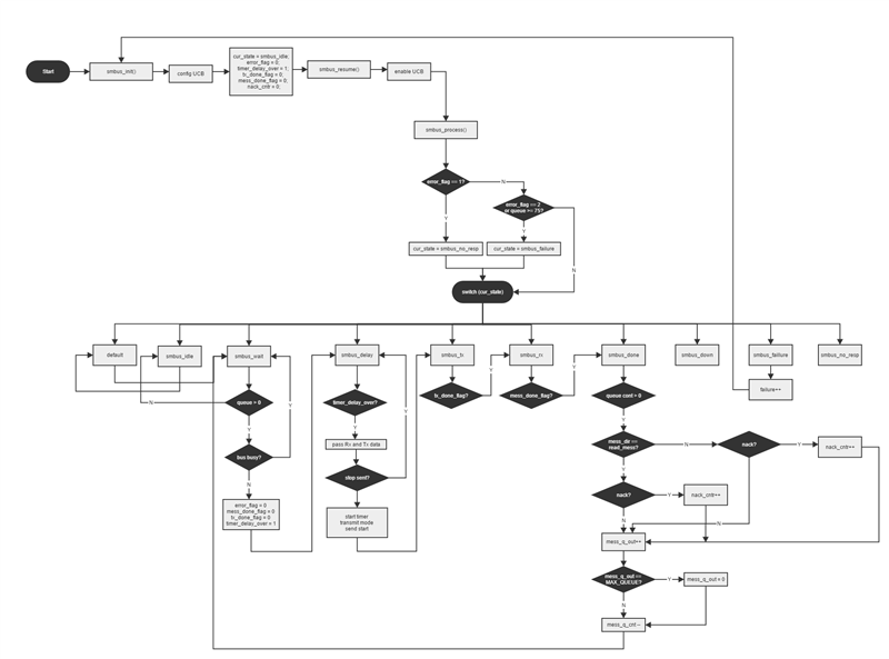
    I'm trying to understand all the code you provide to use in my project. Below is the flowchart I have until now.

    I have a few questions:

    - How should I handle a smbus_failure? I'm going to smbus_init() and smbus_resume() in order to do so. Is there a better way to reinitialize the communication?

    - The timer_delay_over flag never goes to zero after the first run. Why? What is the function of this flag for the code?

    Thanks,

  • HI Mauro,
    Unfortunately, I do not have time to look at the flow chart that you provided. I think that a state diagram would be better suited to represent the logic of the SMBus state machine. It would be easier to understand.

    Mauro Basquera said:
    - How should I handle a smbus_failure? I'm going to smbus_init() and smbus_resume() in order to do so. Is there a better way to reinitialize the communication?

    I reset my SMBus. So yes, SMBus_init() followed by SMBus_resume would be tbe best way. We had an issue where the 25ms timeout was not always resspected by the BQ78350, so we would fall into this condifition often. We fixed the issue by increasing the delay to 26ms.

    Mauro Basquera said:
    - The timer_delay_over flag never goes to zero after the first run. Why? What is the function of this flag for the code?

    I was not the last one that worked on the code, but you are right that it does not seem to be used. The BQ78350 specifies a minimum 2ms delay between SMBus communications. This flag was used to insert that delay. I am not sure what the last person used to implement the delay.

    Regards,

    Michel

  • Hello, Michel.

    Thanks for your clarification.
    I know you must be busy, I just showed the flowchart to ease any possible explication.

    There is no "Verify Answer" option on your responses, that's why I'm not doing that.

    Anyway, thanks again!

    Regards,
  • Hello, Michel.

    I'm trying to use the smbus_writeWord function to update the RemainingCapacity, however the command is not working.

    Do I have to send a command before or after it? I've already checked and the device is is "Full Access Mode".

    unsigned char *dado;
    unsigned char x1;
    
    x1 = 0;
    dado = &x1;
    smbus_writeWord(0x0F,dado);

    I'm a bit confused because I'm able to update the RemainingCapacity through bqStudio, but in the d/s this command is shown as a read-word only.

    And as R/W word at the same time:

    Thanks,

  • Hi Mauro,

    There are few things that seem to be wrong:

    First of all, the 17.17 description says that it is a read-word function (not a read-write). However, you seem to be saying that you can configure it through BQ Studio. This probably needs to be clarified by a TI employee.

    Are you sure that you are not configuring the remaining capacity alarm?
    I would refer you to the forums: see if anybody else asked that question already, if not, post a new question. By asking a new question, other forum users will look and possibly answer your questions (IMO, this thread is way too long and contains too many questions and answers. I like to have one thread, one question, one answer).

    Second., you are trying to send a Word (2 bytes) but you pass an unsigned char (1 byte) to the function. I am not sure what the behaviour of the function will be but most likely, you are sending 1 additional byte of garbage on the SMBus line.

    To make your code more compact, I would suggest using something like this:

    // Depending on your microcontroller, this could be an unsigned int or unsigned short.
    // It's then safer to use uint16_t (sometimes uint16) which is pre-defined for your microcontroller
    uint16_t x1 = 0;
    
    smbus_writeWord(0x0F,&x1);

    Regards,

    Michel

  • Hello, Michel.

    OK, I will try to clarify it with a TI employee.

    Sorry about the long thread, but I'm asking it here because it's related to the code you kindly provided. You can't imagine how much it is helping me. I'm pretty new to embedded programming, you probably already noted that.

    About the solution you suggested, it didn't work. I put it as a char, because the inputs of this function are declared as char. When I put the uint16_t I get a warning: "#169-D argument of type "unsigned short *" is incompatible with parameter of type "unsigned char *"

    void smbus_writeWord(unsigned char addr, unsigned char *data) {
        message *new_mess;
    
        if (smbus_queue.mess_q_cnt < MAX_QUEUE) {
            new_mess = &smbus_queue.mess_q[smbus_queue.mess_q_in];
    
            new_mess->address = BQ78350_ADDR;
            new_mess->mess_dir = write_mess;
            new_mess->is_block = 0;
            new_mess->tx_data[0] = addr;
            new_mess->tx_data[1] = *data;
            new_mess->tx_data[2] = *(data + 1);
    
            //update queue pointers
            smbus_queue.mess_q_in++;
            if (smbus_queue.mess_q_in == MAX_QUEUE) smbus_queue.mess_q_in = 0;
            smbus_queue.mess_q_cnt++;
        }
    }

    I also tried other variations by putting data direct on tx_data[1] and [2] and it didn't work.

    And I pretty sure the command to update the RemainingCapacity is 0x0F, because I'm using it in bqStudio.

    Thank you very much for your help. I really appreciated that.

  • Hi Mauro,

    For your Remaining Capacity issue, try writing to another register to make sure that the write word function is working.

    I used unsigned char * to make the function generic.

    The user can then either use it with a uint16_t (with a cast) or an array of uint8_t. See examples below:

    // With uint16_t
    uint16_t x = 0x1234;
    smbus_writeWord(0x0F, (unsigned char *) &x);
    
    // With an array
    uint8_t y[2];
    y[0] = 0x34;
    y[1] = 0x12;
    smbus_writeWord(0x0F, y);

    It's probably best to use the second method since you control the enddianness (makes the code portable, avoids surprises if your change to a different microcontroller).

    Regards,

    Michel

    EDIT: Also, to make sure what BQ Studio is sending, use a logic analyzer. You will be able to see exactly which command is sent.

  • Hello, Michel.

    Thanks a lot for ur help.

    It happened to be a missing line in smbus_writeWord function.

            new_mess->address = BQ78350_ADDR;
            new_mess->mess_dir = write_mess;
            new_mess->is_block = 0;
            new_mess->tx_cnt = 3;    //I added this line
            new_mess->tx_data[0] = addr;
            new_mess->tx_data[1] = *data;
            new_mess->tx_data[2] = *(data+1);

    I figured it out because I used an oscilloscope and the uC was just sending the bq78350 address and then pulling the line high for any address and data.

    I don't know how it was working on your product, but I added it and it worked pretty well.

    Thanks for your tips!

    Regards,

  • I don't have a lot of experience with SMB (or I2C) but may have some pointers.  First, SMB is some added constraints on top of I2C, so familiarity with I2C is a good starting point.  Without taking a careful look, I don't see the Start, Ack, Nak or Stop bits that I2C requires.  I would suggest looking at slua475.pdf on TIs web site as a good place to start.  

    Also, I'm not sure how many readers will sift through the amount of code you posted.  Or more to the point, I personally wouldn't write that amount of code until I was communicating.  Without digging in, I don't know if you are generating each bit in SW or using and I2C controller, but either way, maybe 20 lines of code should allow you to generate a read request and get a reply.  Until that is working, the rest is a distraction.  Even better would be to do a write request, because it is simpler, but it would have to be something that resulted in observable behavior, so you could tell when it worked.  The simplest write request is only four bytes long.

  • Hello, Wilton.

    Thank you for ur tips.

    Regards,