This thread has been locked.

If you have a related question, please click the "Ask a related question" button in the top right corner. The newly created question will be automatically linked to this question.

BQ34Z100EVM: Failed to update learned status on bqstudio

Part Number: BQ34Z100EVM
Other Parts Discussed in Thread: BQSTUDIO, GPCCHEM, EV2400, BQ34Z100-G1

Hi, I got some problem on bqstudio again.

Here's my setup

Battery Samsung ICR18650-30B (8*3000=24000mAH) (Connected in parallel)

I tried to charge and discharge several time, do as the reference manual suggested. 

But i can't update the status at all.

I definitely have enough rest time, charge to full and discharge to empty. 

Is there any possible factor that can affect learned status update?

  • Hi Ryan Yuen,

    There are many factors that can effect learning status update. Without seeing the logs and the gg.csv file its impossible to determine root cause, however, here are a few commonly run into issues:

    1. Ensure your chemID is properly programmed. This includes using the GPCCHEM tool to determine the proper chemID.
    2. Ensure the device is properly calibrated. With a battery stack voltage of < 5 V, the internal divider may be utilized and VEN = 0
    3. Ensure your design capacity and design energy values are properly set for the device. For a 1S8P configuration design capacity = 8*3000=24000 mAh and design energy = 24000*3.78 = 90720 which is beyond range, so the design energy scale must be utilized. Set design energy scale = 10 which will make design capacity = 2400 cWh and design energy = 9072 cW. Also take care to scale the other parameters identified in table 15 of the datasheet (pg. 31).
    4. Ensure that the FC bit sets when fully charged
    5. Ensure the device fully relaxes after charge
    6. Ensure the device is fully discharged to cell terminate voltage at the constant current rate identified for your chemistry type.
    7. Ensure the device fully relaxes after discharge

    Sincerely,
    Bryan Kahler
  • Hi Bryan,

    I tried to upload the log file. I am not familiar with the upload function. Please let me know if you can read it.

    Ryan

    /cfs-file/__key/communityserver-discussions-components-files/196/4278.18650_5F00_30B_5F00_20180727.zip

  • Hi Ryan,

    Please also send the gg.csv file. Go to the data memory tab and hit export.

    Sincerely,
    Bryan Kahler
  • Hi Ryan,

    Thank you for attaching the gg.csv file. I will analyze these files and provide an update by Friday.

    Sincerely,
    Bryan Kahler
  • Hi Ryan,

    The Ra table on your device is corrupt.

    Please reprogram the device and configure the fields as described in the device datasheet.  Also take care to scale the other parameters identified in table 15 of the datasheet (pg. 31).

    Are there other devices on your I2C bus? If so, please remove the extra devices from the i2c bus to prevent bus contention.

    Is the board custom? If so, and the errors continue to persist, please include the schematic.

    Sincerely,
    Bryan Kahler

  • Hi Bryan, 

    Thanks for the help.

    I just connect the battery with the board directly.

    So, is the procedure something likes: 

    1. Calibration on the current, voltage and temperature.

    2. Setup the parameters (design capacity, design energy etc.)

    3. IT enable, reset

    4. Start the discharge. (When to stop discharge? batlow is set? the battery voltage drop to terminate voltage?)

    5. Rest for 5 hrs. (OCVTAKEN is set, learned status should be 0x04)

    6. IT enable

    7. Charge to Full.(FC is set)

    8. Wait for 5hrs. (OCVTAKEN is set, learned status should be 0x05)

    9. Start to discharge.

    10. Rest for 5 hrs. (OCVTAKEN is set, learned status should be 0x06)

    Thanks for the big help.

    Ryan

  • Hi Ryan,

    Thank you for the image.

    1. Please move the I2C cable to J7 I2C connector. It is currently connected to the HDQ connector.
    2. Please power the device. To power the device (this is a battery simulator), please use a power supply connected to BAT+ (positive lead) and BAT- (ground lead). Use this configuration to program the board initially.

    This process is described in detail, including initial jumper settings in the Quickstart Guide, found here: www.ti.com/.../sluubv2

    After the device is configured, remove the power supply from BAT+ and BAT- and connect your battery to BAT+ and BAT-. Connect your charger / load to BAT+ and PACK-.

    Delete step 6. IT only needs to be enabled once. Then, follow these modified steps:

    1. IT enable, reset

    2. Charge to Full (FC is set)

    3. Rest for up to 5 hrs (OCVTAKEN is set, learned status should be 0x04)

    4. Start the discharge. (Stop discharge when battery voltage drop to terminate voltage)

    5. Rest for 5 hrs. (OCVTAKEN is set, learned status should be 0x05)

    6. Charge to Full.(FC is set)

    7. Wait for 5hrs.

    8. Start to discharge. (Stop discharge when battery voltage drop to terminate voltage)

    9. Rest for 5 hrs. (OCVTAKEN is set, learned status should be 0x06)

    Sincerely,
    Bryan Kahler
  • Hi Bryan,

    I would like to ask is there any problem if I over discharge the battery? Will it cause any failure of the learning cycle?

    Best wishes, 

    Ryan

  • Hi Ryan,

    Over discharging the battery can hurt the battery itself. For a lithium-ion cell, only a 90% DOD drop is required. It is not recommended to exceed a 100% DOD drop.

    Sincerely,
    Bryan Kahler
  • Hello Bryan,

    Is it okay to start the discharge first? Just like bq38z610 ()

    This is the current log file, i noticed that the VOK hasn't set on the charging start. Can the current situation achieve learning status = 0x05?

    20180907 1714.log

  • Hi Bryan,

    Thanks for the reply. I am sorry I keep asking questions. 

    My colleague does the same test by EV2400. The procedure we did as follow

    Program chemistry > Set data flash > Calibration > IT enable, reset > discharge (4.21V -> 3V @1000-2000mA) > rest (5 hrs, until OCVTAKEN is set) -> start to charge (3V -> 4.2V @2000mA) -> rest (5hrs, until OCVTAKEN is set)

    Things go wrong in here. We may accidentally short something and the 34z100gEVM is no response. 

    I would like to know is my colleague did the same procedure? Is it necessary to start from charge to full? Can I have a detailed flag indication? It what bit will set/reset in which stage?failed_batt_log.zip

    I appreciate and thanks for the help from Ti. Hope you all have a nice weekend

    Ryan

  • Also, I noticed that the VOK hasn't set at the beginning of the charging. I thought Once the IT is enable, the VOK will be set automatically. As far as I understand, is it

    start discharge: (set: RUP_DIS, QEN)
    end of discharge: (set: BATLOW, RUP_DIS, QEN)
    start rest: (set: sleep, RUP_DIS, QEN)
    end of rest: (set: sleep, VOK, QEN)
    start charge: (set VOK + QEN)
    end of charge: (set VOK + QEN)
    start rest: (set: sleep, VOK, QEN)
    end of rest: (set: sleep, QEN)
    learned status = 0x05
  • Hi Ryan,

    Please refer to this guide for trouble shooting advice on performing the learning cycle: e2e.ti.com/.../7418.Achieving-The-Successful-Learning-Cycle.pdf

    If the issue persists after following the 7 debug steps in the above guide, could you please explain in more detail by what is going wrong, what has been shorted/where, and what you mean by there is no response from the bq34z100-G1 device?

    Sincerely,
    Bryan Kahler
  • Hi Ti,

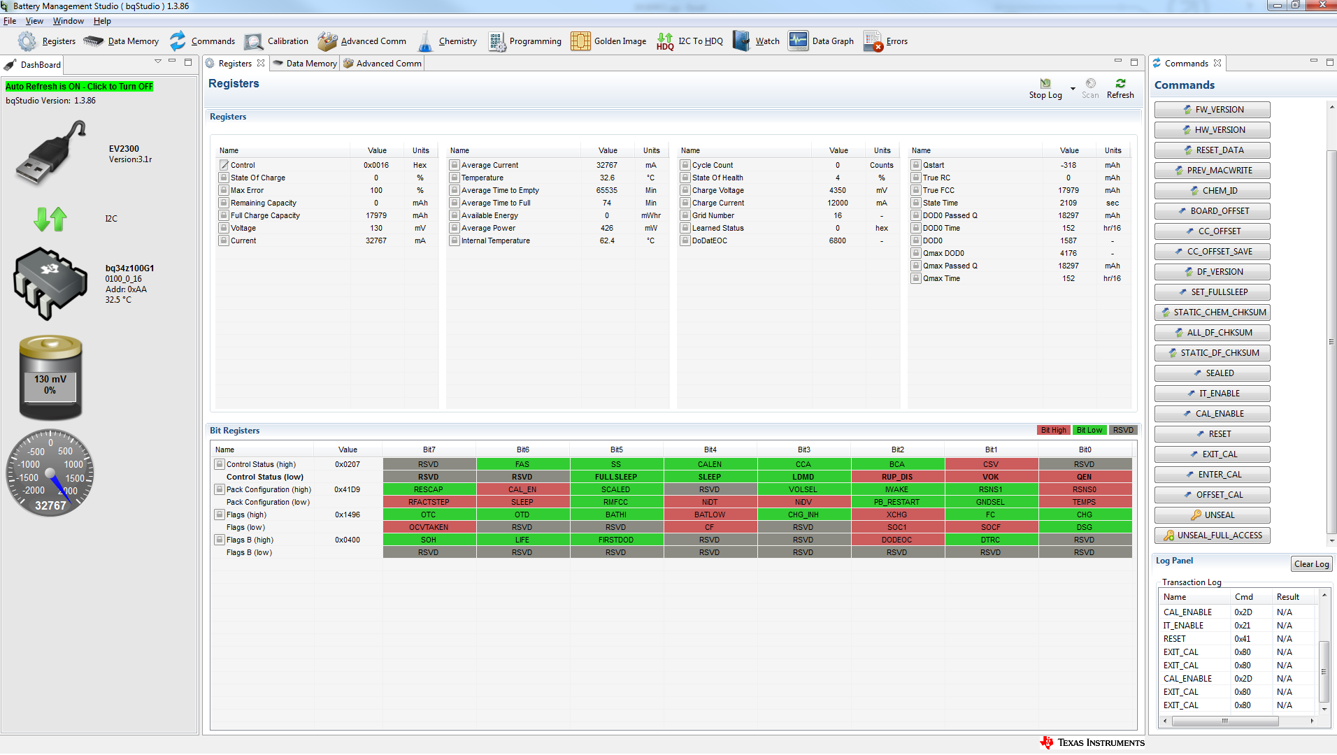
    I re do the process and there are new problems.

    Does that mean the procedure is failed?

    Thanks

    Ryan

    4336.Desktop.zip

  • Hi Ryan,

    The data from the after file appears to be corrupted.  There are several fields with nonsensical data.  

    As seen in your files, the Ra_0x table is complete corrupt.  The flag value is nonsensical.  

    There are also data memory parameters that have changed which the firmware does not change.  For example, "Voltage Divider".

    The low voltage as displayed on your dashboard is a result of the "Voltage Divider" parameter.  This value is converting the voltage with ratio of 0.092 : 1.  This value should not be changed during normal operation of the device.


    The issue appears to occur at sample 29096.  Did the device function after power cycling? 

    Please try reprogramming the device with the stock SREC.  If this does not correct the issue, please describe the sequence of events that occurred.  

    Sincerely,
    Bryan Kahler