This thread has been locked.

If you have a related question, please click the "Ask a related question" button in the top right corner. The newly created question will be automatically linked to this question.

usb to gpio can’t connect ucd9222

Other Parts Discussed in Thread: UCD9222

Hello ;

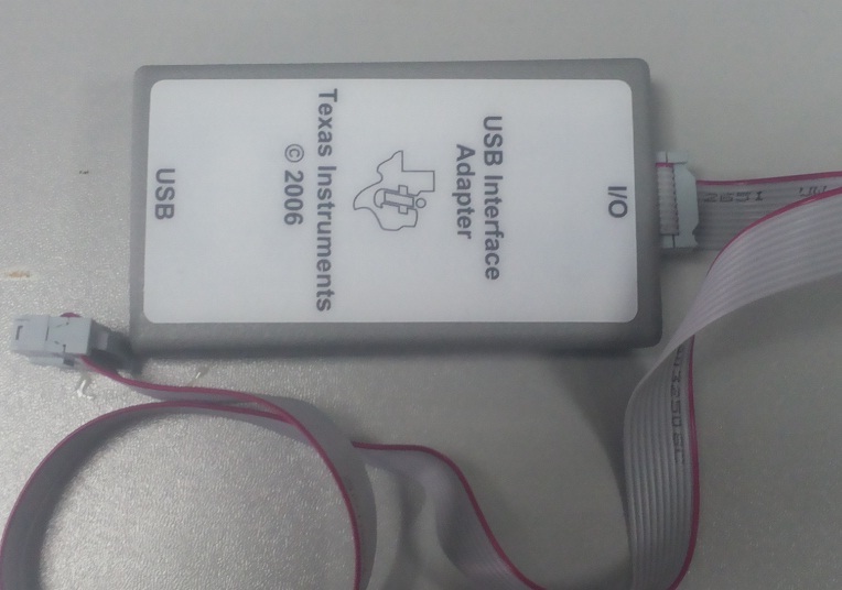
         I buy a usb to gpio,and   want to connect ucd9222,

        use   TI-Fusion-Digital-Power-Designer-2.0.166.exe;

         I connect USB TO GPIO(usb interface adapter)with PC,and the other connect my board PMBUS port;THE green light is bright。

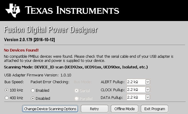
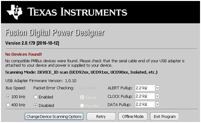
        but  it always say “”no device found ”

       plase  tell me where is the problem。thanks

  • Is the UCD9222 powered? Also, check data and clock waveform and see if they have correct levels. The adapter has programmable internal pull-up resistors. You can adjust the internal pull-up resistor values by GUI.

  • the ucd9222 has been powered. I try adjust the internal pull-up resistor values (the clk, data and alt be set 2.2k). but I measure(disconnect my board) and find that the pin level on the usb adapter is (the clk and alt is high level .but the data is 0 level). whether the usb adapter is abnormal? then I measure my board (disconnect usb adapter) and find that the pin level on the ucd9222 is (the clk and data is high level .but the alt is 0 level) ,I donot know why ,is my board problem? thanks.
  • Data should be high when there is no communication. Maybe you measured a wrong pin?

    You can measure the data and clock lines when GUI is scanning the bus, and see if they have switching waveform.

  • The pin I measured should be right.  pin9 is clk and pin10 is data.

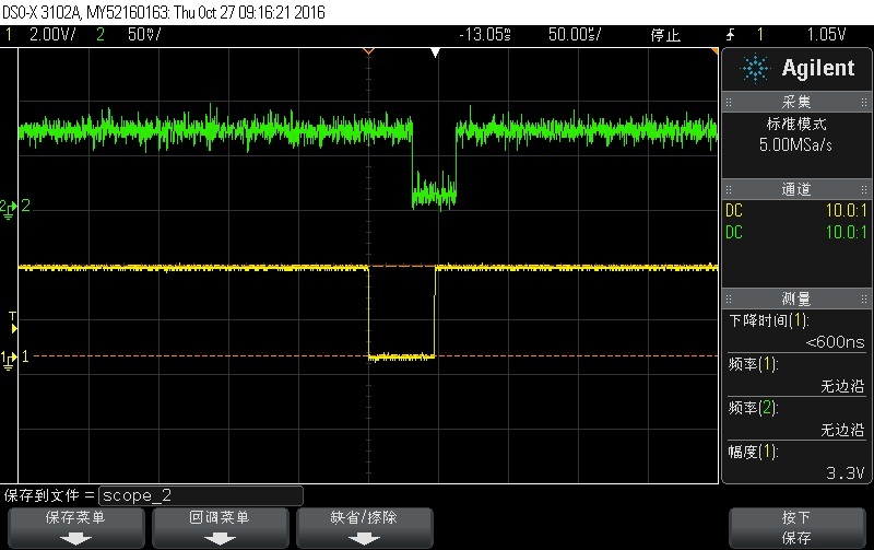
     then I scanning the bus and use the oscilloscope measure(remove my board, just measure from usb adapter)pin 9 (pmbus clk)(yellow) and pin 10 (pmbus data)(green)  in the picture.

    and found that The level of pmbus data is 70mv  it seems that  abnormal .but the pmbus clk is 3.3v , seem normal.

     the usb adapter firmware version is 1.0.10, is it low?

    what other problem should result the pumbus data can't be pulled high?   thanks

  • Hi Star,

    Seemingly there is something wrong with your USB Adapter DATA Pullup configuration, suggested you change the DATA Pullup value, which is found in GUI: File-> USB Adapter Settings -> DATA Pullup, and see how the waveform of DATA PIN changed with the oscilloscope.
    Besides, you could connect with your board, to see how the waveform is in the DATA Pin.

    Thank you.
  • HI FERY:

      I use the  Fusion Design Online  on the desktop.

    The data and clock  pull up can be choosed 2.2kΩ 1kΩ 668Ω and open drain on the  menu.

    I choose 1k, then mesure and find the pin data 's level be 130mv ,and then choose 668 ,the result is 180mv.

    for the clock the result is always 3.3v no matter what size I choose.

    then I connect  the adapter with my board and The result is the same as the adapter no connect with my board .

    I test my board (not connect with adapter pin). the pmbus clock pin and data pin are both 3.3v level.

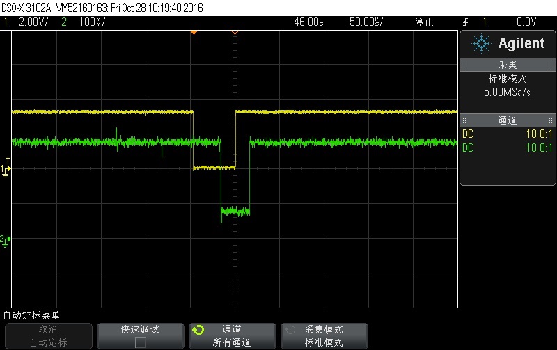
    The picture below is that  I connect  the adapter with my board .clk and adta both are be set 668 on the software menu.

    why the data pin can't be Improved the level ?

    is there something else I need to do?

    thank you .

  • Hi Star,

    As I tested with good USB to GPIO adapter, the DATA voltage is keep 3.3V regardless of pull-up resistor, when not connecting to the board.
    So it may have fault with your USB to GPIO adapter, you could compare it with a normal one.

    Thank you.
  • Thank you very much. I will find a normal adapter to try.
  • Hi  Fery Feng

    NOW The new usb to gpio has been received. and I test the pin without connect any device besides the PC .find that  the DATA pin (pin 10) voltage is keep 0V regardless of pull-up resistor. I donot know why.

  • Hi Star,

    Just make sure the USB to GPIO is powered, and the green LED is on.
    As I tested, the voltage on DATA and CLK is 3.3V.

    Besides, if you connect this USB to GPIO to the board, does it function?

    Thank you.
  • Are you using the same ribbon cable between both adapters?

    Have you tried testing the pin directly from the adapter rather than on the ribbon cable?

  • Hi  Fery Feng:

     I sure the USB to GPIO is powered, and the green LED is on.

    and when  I connect this USB to GPIO to the board, it do not function.

    do I need update the firmware of the USB to gpio. now  th e firmware version of the usb to gpio is 1.0.10 as the picture

     and what is  the  firmware version of  your  usb to gpio ?   thank you .

  • Firmware version 1.0.10 for USB-to-GPIO is fine.

    Did you verify that the ribbon cable is OK?

    You have indicated that the data and clock lines on the board are OK when the adapter is disconnected, which means you must have pullups on your board to a locally generated 3V3 source (the Alert line could be low if there was a condition present on the controller that would activate this pin with or without the adapter connected)

    So it sounds as if there is some interaction between the board and the adapter.

    Lets go over the connections on the ribbon cable from the adapter:

    1) Pin 6 should be connected to GND on your board

    2) Pin 7 is the Control Pin (used to enable/disable the controller), this is optional

    3) Pin 8 is the Alert Line which is driven low by the controller when a fault/warn condition is present

    4) Pin 9 is the CLK

    5) Pin 10 is DAT

    6) Pin 5 is 3V3 LDO reference voltage from the adapter, this should not be connected to a 3V3 source on your board,

    Can you provide the schematic circuit for the connection between the ribbon cable and the UCD9222?

  • HI brad:
    as your Suggestion,I DIRECT Connect the five lines from the adater without use ribbon cable . then It can find the device. so thank you very much. It is the problem of the ribbon cable.
    Thank you very much.