This thread has been locked.

If you have a related question, please click the "Ask a related question" button in the top right corner. The newly created question will be automatically linked to this question.

CSD85302L: Reflow Soldering Issue

Part Number: CSD85302L

Can anyone Help,

I cannot prevent solder balls forming and solder migrating from the pads of 1 and 3 of this device during reflow.

I am seeing solder pulling away from these pads but staying connected to the pads.

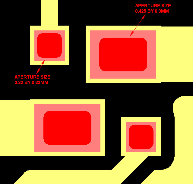
I am using a 3 thou stencil with aputrues cut as per the recomendation in the data sheet and am using type 4 lead free solder paste. 

Please help

Kind regards

Darren

  • Darren,
    Are you using a stencil thickness of 0.100 mm?

    Is the mounting automated?

    On thing our packaging engineer suggested was to try to "lower down a placement force so that you don’t squeeze out the solder". I can ask him to clarify if need be.
  • Hi Brett,

    Thank you for kindly sparing the time to respond to my post.

    I am using a 0.0762mm (3 thou) stencil thickness.

    The component is being  mounted aoutomaticly using Samsung SM482 placement machines.

    I made sure that the component is just being placed on to the paste rather then being pushed into the paste and have verifiyed the paste displacement by x-ray before reflow. their is virtually no paste displacement before reflow.

    I am at a loss as to what is caursing this issue.

    I have attched an image of the stencil apertures  we are using against the mask defined coper lands, if you have any comments on this I would be grateful for any help and suggestions

    Thanks Darren

  • Darren,
    Our packaging experts think you need to adjust the reflow profile to reduce the soaking period.
  • Would you mind sending your reflow conditions / profile? Then we can have our packaging team take a look.
  • Hi Brett,

    I do not seem to be able to insert a file or an image of my reflow profile.

    We are using 8 zone convection oven

    The profile is as follows:

    26c to 150c 79 seconds

    150c to 200c 118 seconds

    200c to 217c 15 seconds

    Above 217c for 68 seconds

    Max temp 246c

    DO you have an comments regarding the stencil image in my prevouse reply?

    Kind Regards

    Darren

    8490501 Reflow Profile.pdf

  • Darren,

    Our packaging engineer recommends you try following this. I will follow up on the stencil comments. 

  • From our packaging engineer: "They followed the stencil opening so it should be fine. The balling issue is more caused by reflow. The other is how clean the stencil is when redoing the printing"
  • Hi Brett,

    I am not able to follow the reflow profile you have kindly provided as it does not show enough detial.

    Would it please be possible to provide more detial in particular time zones between the tempertures below.

    • Ambient to 150c
    • 150c to 217c
    • time above 217

    Regarding our stencil aperture size for the 2 larger lands of this device we have not followed the data sheet recomendations and have made these apertures smaller than recommended.

    Would it please be possible for your packaing engineer to provide his view on the possiblity of this caursing an issue, is it possible that these 2 lands are pulling the device closer to the PCB as the solder on these 2 lands has more room to spread during reflow where as the smaller 2 lands do not have any wehre for the solder to go?

    Kind Regards

    Darren 

  • Darren,
    The accompanying times would be as follows:

    Ramp rate: 3degC/sec Max
    Preheat: 150 to 180degC for 60 to 120sec

    Time above liquidus: 220deg, 30 to 90sec

    Peak Temp: 260deg

    Time Within 5deg of Peak Temp: 10 to 20sec

    Ramp Down Rate: 6degC/sec Max

    "Our pad size was optimized to prevent tilting…
    So possible cause would be tilting, that is only one, otherwise we need to see all of his dimensions"
  • Hi Brett,

    I have attached a file that detials the dimentions of the land, solder mask openings and stencil stencil apertures we have used.

    Would it be possible to provide me with the dimentions of the lands, solder mask openings and stencil apertures you have used.

    Kind regards

    Darren

     Q1 Copper Resist & Stencil.xlsx

  • Darren,
    I am not sure that a full simulation is something we can support at this time. I apologize.

    Again we need to emphasize that if the datasheet dimensions are not followed, the most likely issue you would encounter is package tilting but not the balling that you encountered which is driven by reflow optimization.
  • Hi Brett,
    Many thanks for all your help and advice with this issue.
    I am note due to assemble this product again for another month so are unable to assess if altering the reflow profile will eliminated this issue.
    If possible I would like to keep this issue open until I have assembled the next batch and are able to confirm if altering the reflow profile has eliminated this issue.

    Kind regards
    Darren
  • Darren,
    No problem. Please feel free to come back once you attempt the new reflow profile. As a policy, we are supposed to "close" threads when there may not be any traffic on them for some time, and for the time being I am going to consider your issue resolved. I know you probably get some notification asking you to confirm - you can just ignore that message for now.

    But you still have 60 days to reopen the thread if there proceeds to be an issue. Or if you come back in three months and the thread is closed permanently, you can either start a new thread and link to this one (I'll still be the one answering) or better yet, send me a friend request on E2E, we can exchange emails, and work the issue offline.